Energy-saving speed-regulating permanent magnet driver

A drive and permanent magnet technology, applied in the field of drives, can solve problems such as no buffer starting device, motor stalling, affecting work progress, etc., to achieve soft start, reduce vibration, and solve the effects of stalling

Inactive Publication Date: 2012-11-21
宁波市北仑地勤工贸有限公司
View PDF0 Cites 0 Cited by
  • Summary
  • Abstract
  • Description
  • Claims
  • Application Information

AI Technical Summary

Problems solved by technology

[0002] At present, after the motor is powered on, it starts directly under the state of full load, without any buffer starting device, which may easily cause the motor to stall
That is to say, when the motor is normal and the power supply of the motor is normal, the motor cannot work and run normally due to the heavy load of the motor. At the same time, frequent motor stalls will shorten the life of the equipment and lead to low work efficiency. , affecting work progress
[0003] In addition, the existing permanent magnet drive works at 1,000 kilowatts, and consumes 1 kilowatt-hour of electricity in one hour, saving energy by up to 10% to 15%. When it is in standby, because the motor is always powered on, the permanent magnet drive also consumes power all the time. , poor energy saving
When the motor is not working at full load, it will also consume the same amount of electricity, which cannot save electricity

Method used


Image

  • Energy-saving speed-regulating permanent magnet driver
  • Energy-saving speed-regulating permanent magnet driver
  • Energy-saving speed-regulating permanent magnet driver

Examples


Embodiment Construction

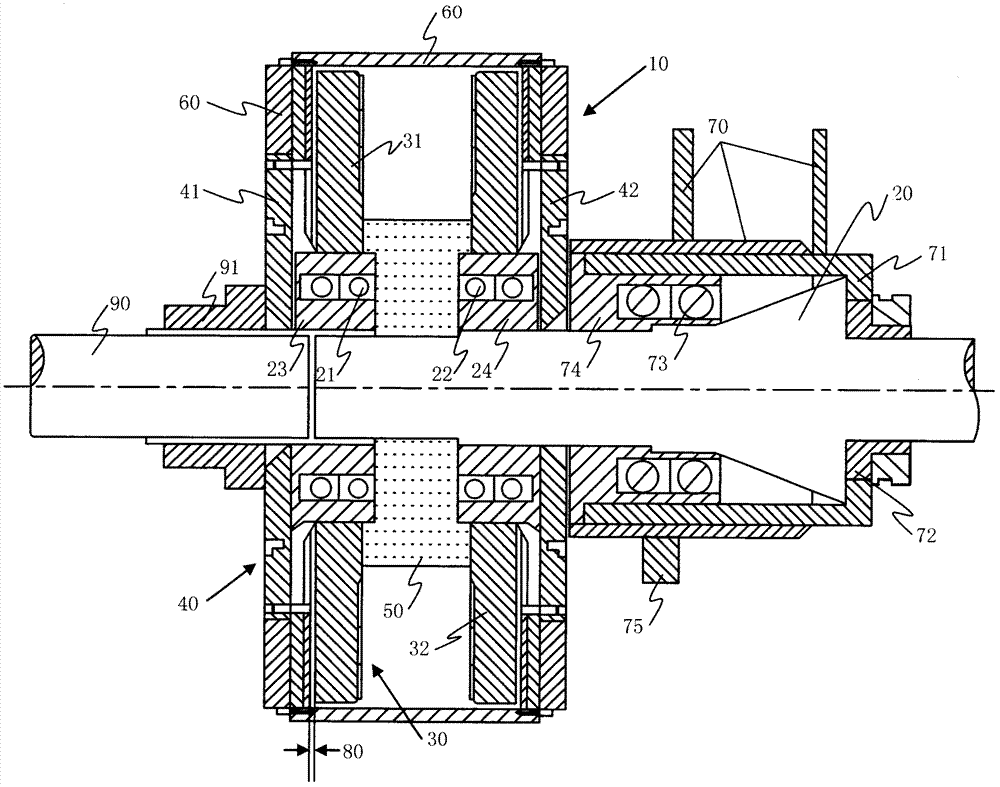
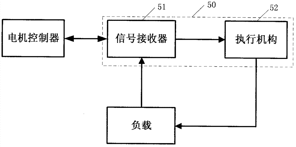
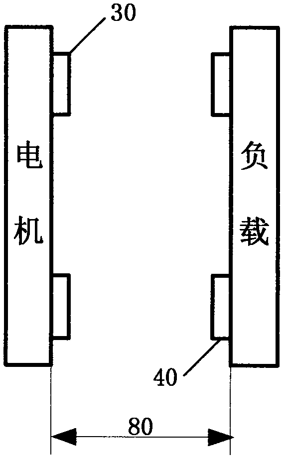
[0010] An energy-saving speed-regulating permanent magnet driver, comprising a speed-regulating device 10, the speed-regulating device 10 is arranged along the axial direction of a motor shaft 90 and a load shaft 20, the motor shaft 90 and the load shaft 20 are on the same central axis, the motor shaft 90 There is a gap between it and the load shaft 20. The speed regulating device 10 includes a copper rotor 30, a permanent magnet rotor 40 and a controller 50. The copper rotor 30 is fixed on the load shaft 20, and the permanent magnet rotor 40 is fixed on the motor through a bracket 60. The copper There is an air gap 80 between the rotor 30 and the permanent magnet rotor 40, such as figure 1 shown.

[0011] Such as figure 1 As shown, the load shaft 20 is also provided with a base 70 for supporting the load shaft 20, the base 70 is provided with a through hole for the load shaft 20 to pass through, the base 70 is provided with a copper sleeve 71, the base 70 70 is fixedly conn...


PUM


Abstract

The invention relates to an energy-saving speed-regulating permanent magnet driver, which comprises a speed-regulating device. The speed-regulating device is arranged along an axial direction of a motor shaft and a load shaft; the motor shaft and the load shaft are positioned on the same central axis; and a gap is formed between the motor shaft and the load shaft. The speed-regulating device comprises a copper rotor, a permanent magnet rotor and a controller, wherein the copper rotor is fixed on the load shaft; the permanent magnet rotor is fixed on the motor through a bracket; and an air gapis formed between the copper rotor and the permanent magnet rotor. When the motor rotates, the motor drives the permanent magnet rotor to rotate and induction current is formed in the permanent magnet rotor, an induction field is generated in the air gap, and the induction field makes the copper rotor rotate along with the induction field to realize torque transmission. Meanwhile, the width of the air gap between the copper rotor and the permanent magnet rotor is regulated by the controller, and the rotating speed of the loading end can be changed. The energy-saving speed-regulating permanentmagnet driver has the advantages of no mechanical connection between the motor shaft and the load shaft, capacity of realizing wireless variable speed operation, high efficiency, automation and energy conservation.

Description

technical field [0001] The invention relates to a driver, in particular to an energy-saving speed-regulating permanent magnet driver. Background technique [0002] At present, after the motor is powered on, it is directly started under the full load state without any buffer starting device, which may easily cause the motor to stall. That is to say, when the motor is normal and the power supply of the motor is normal, the motor cannot work and run normally due to the heavy load of the motor. At the same time, frequent motor stalls will shorten the life of the equipment and lead to low work efficiency. , affecting work progress. [0003] In addition, the existing permanent magnet drive works at 1,000 kilowatts, and consumes 1 kilowatt-hour of electricity in one hour, saving energy by up to 10% to 15%. When it is in standby, because the motor is always powered on, the permanent magnet drive also consumes power all the time. , poor energy saving. When the motor is not working...

Claims


Application Information

Patent Timeline
Patent Type & Authority Patents(China)
IPC IPC(8): H02K49/10
Inventor 陈传松
Owner 宁波市北仑地勤工贸有限公司
Why Eureka
Try Eureka