
Downhole device for pumping well

A technology for pumping wells and suits, which is applied in wellbore/well components, sealing/package, earthwork drilling and production, etc. It can solve the problems of well site pollution and function as usual, so as to reduce operating links, shorten operating hours, and save oil production The effect of production costs

Active Publication Date: 2018-10-23
牡丹江市金环石化设备有限公司
View PDF16 Cites 0 Cited by
  • Summary
  • Abstract
  • Description
  • Claims
  • Application Information

AI Technical Summary

Problems solved by technology

[0003] The invention provides a downhole device for an oil pumping well with the functions of pipe string anchoring, preventing hot washing water from pouring into the oil layer, and blowout prevention and oil drainage, so as to solve the problem of high-pressure oil well fluid overflow during the process of oil well inspection and pumping up and down pipe strings. For the problem of well site pollution caused by the ground, the functions of anchoring the pumping well string, wax cleaning and hot washing water seal, checking the oil in the pumping string during the process of pumping the string, and controlling the oil overflow of the high-pressure oil well inspection pump are integrated. In one piece, and the downhole device can stay downhole once with the oil well pump downhole, no need to replace it when the pump is checked again, and the function of the newly installed oil well string is still the same after insertion

Method used


Image

  • Downhole device for pumping well
  • Downhole device for pumping well
  • Downhole device for pumping well

Examples


Embodiment Construction

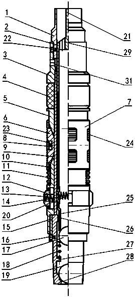
[0018] Below with the present invention as figure 1 The optimization scheme shown is taken as an example to further illustrate the technical scheme of the present invention.

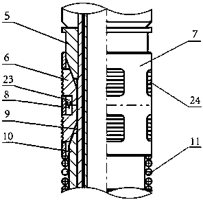
[0019] The transition joint 1 at the top of the device of the present invention is fixedly connected with the lower end of the oil well pump, and sent into the well together with the oil extraction string. After reaching the predetermined position, the oil extraction string is rotated to transmit the torque power from the transition joint 1 through the upper joint 3, The central tube 9 is transferred to the helical sleeve 15 to drive the helical sleeve 15 to rotate. Since the helical sleeve 15 is threadedly connected to the lower cone 10, the relative rotation between the helical sleeve 15 and the lower cone 10 makes the lower cone 10 has an upward displacement relative to the central tube 9, and the tooth block 6 is squeezed by the upper cone 5 and the lower cone 10 through the upper and lower slopes a...


PUM


Abstract

The invention provides a downhole device of an oil pumping well. The device of the oil pumping well has the functions that a pipe column is anchored, hot washing water is resisted to be poured into an oil layer, and the anti-spraying and oil drainage effects are achieved. The downhole device comprises a transition connector (1), a center pipe (9), an upper connector (3), a rubber cylinder (4), an upper cone (5), an anchoring tube (7), a lower cone (10), a screw shell (15), an upper valve main body (2), an upper valve ball (17), a valve ball spring (18), a lower valve ball (19), a block tooth (6), a block tooth spring (8), a large friction block (12), a large friction block spring (13), a small friction block (14) and a small friction block spring (20). According to the downhole device of the oil pumping well, the problem of well site pollution caused by well liquid spraying and gushing towards the ground during pump checking of the high-pressure oil well is solved, the functions that the pipe column is anchored, the hot washing water is prevented from being poured into the oil layer, oil liquid in the pipe column is discharged in the pump checking process, and the oil liquid is controlled to spray and gush are integrated, delivering into the well at a time is achieved, and the well does not need to be lifted during pump checking; and in the whole process of downhole serving in the production period, working links are effectively reduced, the working man-hour is shortened, oil pumping production cost is reduced, and oil pumping production efficiency is improved.

Description

technical field [0001] The invention relates to an oil pumping well downhole device, in particular to an oil pumping well downhole device which has the functions of anchoring a pipe string, preventing hot washing water for wax removal from pouring into an oil layer, and preventing blowout and draining oil. Background technique [0002] At present, most of the operations such as anchoring the oil extraction string, running the packer to prevent the hot water from entering the oil layer, installing the drainer and the blowout preventer in the oil production of the oilfield are all independently completed by a single process and multiple processes, sometimes even requiring The pipe string has to be tripped many times, the construction process is many, the operation cycle is long, and the cost of downhole tools is high. Invention patent CN201410702656.8 discloses "a tubing anchor with triple functions". Completed during the process, it improves work efficiency, saves production...

Claims


Application Information

Patent Timeline
Patent Type & Authority Patents(China)
IPC IPC(8): E21B33/127
CPCE21B33/127
Inventor 李青李红星王梅张维刚王占刚胡志洋李秋谭春雨熊韦
Owner 牡丹江市金环石化设备有限公司
Learn More