
Hydrocyclone group

A hydrocyclone and cyclone technology, which is applied to cyclone devices, devices whose axial directions of cyclones can be reversed, etc., can solve the problem of increasing the amount of steel components, increasing construction investment, and increasing the height difference of the workshop. problems, to achieve the effect of improving efficiency, reducing construction investment, and reducing operation links

Pending Publication Date: 2018-06-29
CHINA ENFI ENGINEERING CORPORATION
View PDF0 Cites 2 Cited by
  • Summary
  • Abstract
  • Description
  • Claims
  • Application Information

AI Technical Summary

Problems solved by technology

Due to the use of the slurry distributor to increase the amount of steel used in the components, and at the same time, an additional layer of operating platform is added, which increases the height difference of the plant and increases the project construction investment

Method used


Image

  • Hydrocyclone group
  • Hydrocyclone group
  • Hydrocyclone group

Examples


Embodiment 1

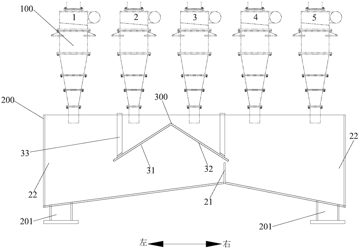
[0043] by figure 2 For example, the group of hydrocyclones is arranged linearly, and the grit chamber is formed into a long strip extending along the direction of arrangement of multiple cyclones, and there are 5 hydrocyclones, which are marked as 1 from left to right No., No. 2, No. 3, No. 4 and No. 5, of which 3 are in operation and 2 are in standby, and assuming that the process requires that the distribution ratio of grit and slurry in the hydrocyclone group is 1:2, of which figure 2 As shown, the left grit outlet distributes 2 / 3 of the grit slurry, and the right grit outlet distributes 1 / 3 of the slurry. figure 2 As shown in the running status of No. 1, No. 2 and No. 3 cyclones (No. 4 and No. 5 standby), the slurry distributor moves between No. 2 and No. 3 cyclones. At this time, the grit-set slurry in No. 1 cyclone Directly enter the left grit chamber of the grit chamber, the grit slurry in the No. 2 cyclone enters the left grit chamber in the grit chamber through th...

Embodiment 2

[0045] refer to Figure 4 , the hydrocyclone group is arranged in a ring, and the grit box forms a ring extending along the arrangement direction of multiple cyclones (the bottom of the grit box is a ring structure inclined to one side), and has 10 Cyclone, of which 6 are running and 4 are standby, the fixed baffle is installed in the form of a plug-in plate, and there are 3 installation slots, which can be installed in different positions to change the flow direction of the upper cyclone grit chamber; the bottom of the grit chamber Two grit outlets are arranged at intervals at the lowest part of the part, and the fixed baffle between the two grit outlets is fixed by welding. The outlet is discharged; the slurry distributor can move along the circumference on the two walls of the grit box to adjust the grit flow direction of the upper cyclone to a greater extent. Assuming that the process requires the grit distribution ratio of the hydrocyclone group to be 1:2, the inner grit...


PUM


Abstract

The invention discloses a hydrocyclone group, which comprises a plurality of hydrocyclones, a sand setting box and a movable ore pulp distributor moving along the layout direction of the plurality ofhydrocyclones, wherein the sand setting box is arranged below the plurality of hydrocyclones for containing sand setting ore pulp which flows out of the plurality of hydrocyclones; a fixed baffle is arranged in the sand setting box to divide the lower part of the inner cavity of the sand setting box into at least two separated sand setting chambers; in addition, the sand setting box is provided with at least two set sand outlets corresponding to the sand setting chambers; the ore pulp distributor is arranged in the sand setting box and is positioned between the fixed baffle and one part of hydrocyclones for distributing the set ore pulp to at least two sand setting chambers at a ratio. Therefore, the hydrocyclones have an ore pulp distribution function, so that an ore pulp distributor operation platform is omitted in plant configuration design, the height difference of a whole ore grinding factory is lowered, and investment is lowered.

Description

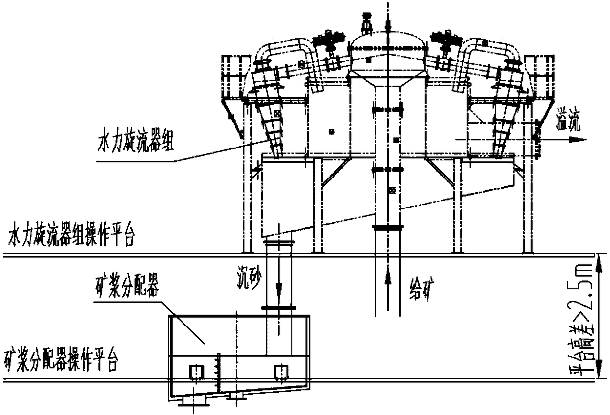
technical field [0001] The invention belongs to the technical field of mineral processing, in particular, the invention relates to a hydrocyclone group. Background technique [0002] At present, the beneficiation process of many mines, especially gold and rare and precious metal mines, often inserts gravity separation operation in the grinding circuit. Select a device. At present, the common method for sand settling and ore separation of the hydrocyclone group is to provide a slurry distributor under the hydrocyclone group, and use the slurry distributor to separate a certain proportion of the slurry to the gravity separation equipment (configuration such as figure 1 shown). [0003] In the prior art, there is only one outlet for sand settling in the hydrocyclone set, and an independent ore slurry distributor is mainly used to separate the sand settling, which is arranged under the hydrocyclone set. In the design of the plant, it is necessary to add an operating platform ...

Claims


Application Information

Patent Timeline
Patent Type & Authority Applications(China)
IPC IPC(8): B04C5/28B04C5/181
CPCB04C5/181B04C5/28
Inventor 高立强孙明俊何荣权冯建伟杨少燕梅志
Owner CHINA ENFI ENGINEERING CORPORATION
Learn More