
Socket type rebar cage structure in steel pipe column and connection method of socket type rebar cage structure

A construction method and steel cage technology, applied in the direction of structural elements, columns, pier columns, etc., can solve problems such as potential safety hazards, inability to apply steel cage construction, and existence of steel pipe column operating environments, so as to ensure the safety of construction operations and increase safety Coefficient, the effect of firm and reliable connection

Active Publication Date: 2017-05-31
CHINA CONSTR EIGHT ENG DIV CORP LTD
View PDF8 Cites 0 Cited by
  • Summary
  • Abstract
  • Description
  • Claims
  • Application Information

AI Technical Summary

Problems solved by technology

[0004] The purpose of the present invention is to overcome the defects of the prior art, to provide a socket-type reinforcement cage structure and its construction method in the steel pipe column, and to solve the inability to construct the reinforcement cage in the steel pipe column in the prior art. It is applied to the construction of steel cages in steel pipe columns with narrow inner cavity space and the safety hazards in the working environment of steel pipe columns

Method used


Image

  • Socket type rebar cage structure in steel pipe column and connection method of socket type rebar cage structure
  • Socket type rebar cage structure in steel pipe column and connection method of socket type rebar cage structure
  • Socket type rebar cage structure in steel pipe column and connection method of socket type rebar cage structure

Examples


Embodiment Construction

[0031] The present invention will be further described below in conjunction with the accompanying drawings and specific embodiments.

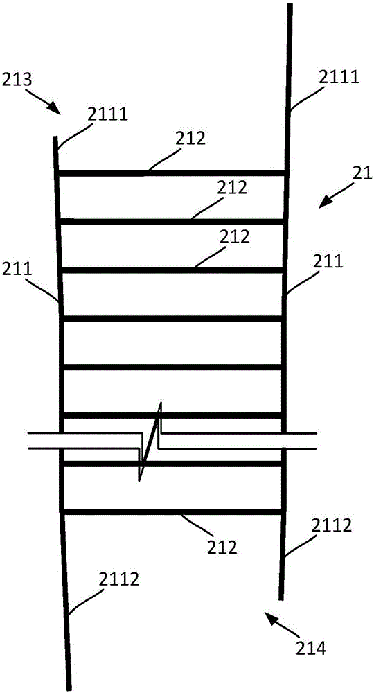
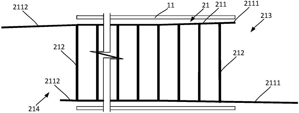
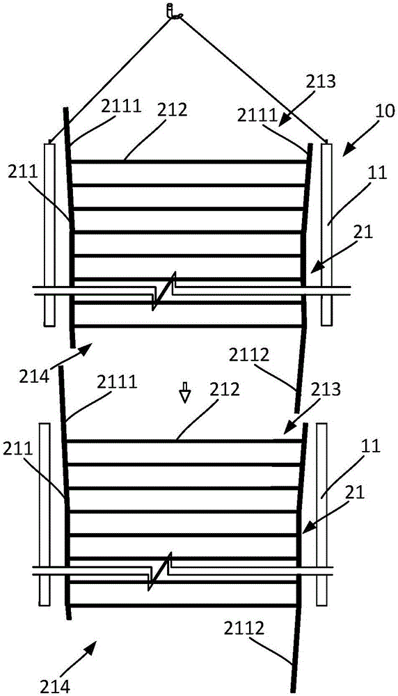
[0032] The present invention provides a socket-type reinforcement cage structure in a steel pipe column and a construction method thereof. It is used for the construction of steel pipe columns with narrow inner cavity space and the poor working environment of the inner cavity will easily cause safety hazards. The invention provides a socket-type reinforcement cage structure. The upper and lower reinforcement cage units are connected by plugging each other, and the small end of the upper reinforcement cage unit is inserted into the large end of the lower reinforcement cage unit, so that The construction of the steel cage structure is simple and convenient, which saves the existing operation steps of fixed connection, prevents workers from going down into the steel pipe column, improves the safety factor of construction, and avoids potential safe...


PUM


Abstract

The invention relates to a socket type rebar cage structure in a steel pipe column. The socket type rebar cage structure comprises a plurality of rebar cage units which are arranged in the steel pipe column and connected with one another in an inserted mode. Each rebar cage unit comprises longitudinal ribs vertically arranged at the edge of the rebar cage unit at intervals and stirrups arranged on the peripheries of the longitudinal ribs in a hooping mode. A large end is formed in the position, at the top end of the corresponding rebar cage unit, of each longitudinal rib. A small end is formed in the position, at the bottom end of the corresponding rebar cage unit, of each longitudinal rib. In every two adjacent rebar cage units, the small ends located on the upper rebar cage unit are inserted in the large ends located on the lower rebar cage unit. According to the socket type rebar cage structure in the steel pipe column, the rebar cage structure is formed through the rebar cage units which are connected with one another in the inserted mode, in this way, workers do not need to descend into the steel pipe column to conduct operation when a rebar cage is installed in the steel pipe column, the problem that the operation space cannot be provided due to the narrow space in the steel pipe column is solved, the potential safety hazards caused by the bad operation environment of an inner cavity of the steel pipe column are also avoided, the construction operation safety of the steel pipe column is ensured, and the construction safety coefficient is increased.

Description

technical field [0001] The invention relates to the technical field of structural engineering, in particular to an inner socket-type reinforcement cage structure of a steel pipe column and a construction method thereof. Background technique [0002] The concrete-filled steel tube column has a large supporting strength, and it is widely used as the main force-bearing structure in the building structure. [0003] The existing construction method of steel pipe concrete column usually adopts hoisting the steel pipe column first, and then constructing the reinforcement cage inside the steel pipe column. When constructing the reinforcement cage, it needs to be manually lowered into the steel pipe column, and the sleeve is used one by one at the bottom of the steel pipe column. The longitudinal reinforcement is connected, and then the stirrup is bound to form a reinforcement cage located in the steel pipe column. There is also a method of tying the reinforcement cage units on the ...

Claims


Application Information

Patent Timeline
Patent Type & Authority Applications(China)
IPC IPC(8): E04C3/34E04C5/06
CPCE04C3/34E04C5/0604
Inventor 孙加齐王宜彬邢亚飞王代兵康晋宇杨明龙汤淼齐磊
Owner CHINA CONSTR EIGHT ENG DIV CORP LTD
Learn More