
Base seismic isolation system of transformer

A basic shock isolation and transformer technology, applied in basic structure engineering, protection devices, buildings, etc., can solve the problem of amplifying transformer vibration and structural noise, the small tensile capacity of rubber shock-isolation bearings, changing the basic dynamic characteristics of transformers and anti-overturning Ability and other issues

Inactive Publication Date: 2017-05-31
TONGJI UNIV
View PDF9 Cites 5 Cited by
  • Summary
  • Abstract
  • Description
  • Claims
  • Application Information

AI Technical Summary

Problems solved by technology

In summary, the above-mentioned patents all use rubber isolation bearings to isolate the transformer base. The size of the rubber isolation bearings is closely related to the quality of the isolation transformer. The quality of the transformer is generally smaller than that of the building structure. To achieve the ideal isolation The size and stiffness of the rubber bearing are small, and the stability is poor. Therefore, the rubber isolation bearing will change the basic dynamic characteristics and anti-overturning ability of the transformer in normal operation, amplify the vibration of the transformer itself and structural noise, and then affect the transformer. normal working performance
The vibration-isolated transformer has a high center of gravity. Under the action of an earthquake, the transformer is easy to overturn, while the tensile capacity of the rubber vibration-isolation bearing is very small, which is likely to cause serious overturning damage to the transformer as a whole.

Method used


Image

  • Base seismic isolation system of transformer
  • Base seismic isolation system of transformer
  • Base seismic isolation system of transformer

Examples


Embodiment

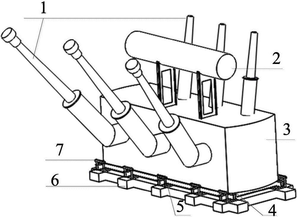
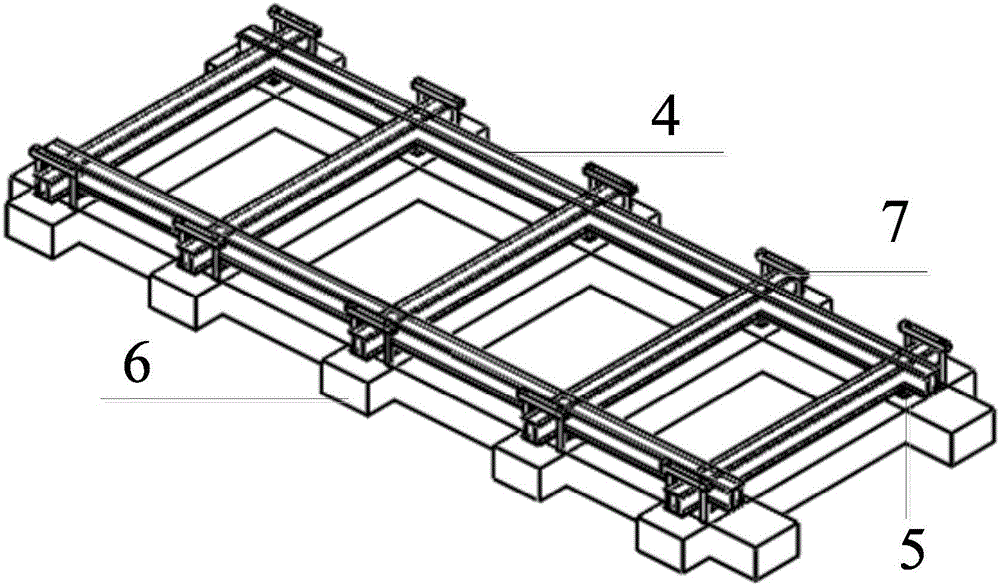
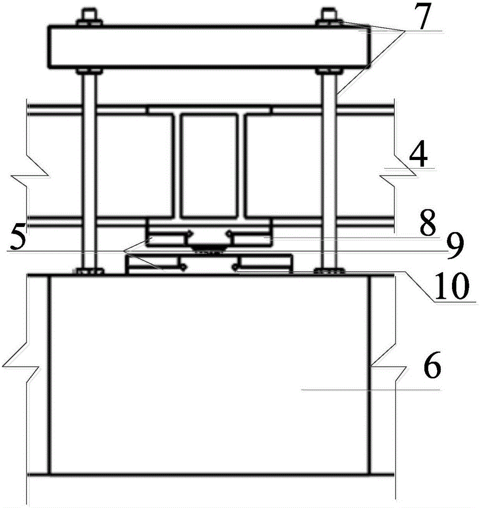
[0039] A transformer foundation isolation system, its structure is as follows figure 1 and figure 2 As shown, it includes a bracket 4 for fixedly installing the transformer and a base 6 fixed on the ground structure. The transformer on the bracket 4 mainly includes a transformer box 3, an oil conservator 2 and a transformer bushing 1. Between the bracket 4 and the base There are also multiple friction pendulum mechanisms that make the two relatively move between the 6, and its structure is as follows: Figure 4 and Figure 6 As shown, the multiple friction pendulum mechanism includes several multiple friction pendulum supports 5 distributed on the edge of the support 4 and the base 6, and each multiple friction pendulum support 5 includes an upper support plate 8, a lower support plate 10 and The middle slider 9, the upper bearing plate 8, and the lower bearing plate 10 are respectively connected to the bracket 4 and the base 6, and the upper and lower end surfaces of the m...


PUM


Abstract

The invention relates to a base seismic isolation system of a transformer. The base seismic isolation system comprises a bracket (4) used for mounting the transformer and a base (6) fixed on a ground structure. Multiple friction pendulum supporting seats (5) and a pulling resistant device (7) are further mounted between the bracket (4) and the base (6), wherein the multiple friction pendulum supporting seats enable the bracket (4) and the base (6) to slide horizontally, and the pulling resistant device (7) restrains the vertical movement of the bracket (4) and the base (6). Compared with the prior art, according to the base seismic isolation system, the seismic effect can be effectively reduced, the vibration of sleeves on the upper portion of the transformer is reduced, and the sleeves can be prevented from damage; meanwhile, the seismic isolation period of the multiple friction pendulum supporting seats (5) is independent of the quality of seismic isolation equipment, the parameters of the seismic isolation design are simple, and the selection range is large; and different seismic isolation design targets can be achieved under different design earthquake levels by optimizing the seismic isolation parameter design, and the base isolation system can be applied to seismic protection of power transformation equipment of power transformers, converter transformers, electric reactors and the like.

Description

technical field [0001] The invention relates to a shock isolation system, in particular to a transformer foundation shock isolation system. Background technique [0002] With the development of my country's power transmission and transformation projects in the direction of high voltage, ultra-high voltage and ultra-high voltage, a large number of key transformation equipment - large (ie high voltage, ultra-high voltage and ultra-high voltage) power transformers and Converter transformer. These large transformers have large volume and quality, high cost, and a large number of bushings are installed on them. In previous earthquakes, due to the power amplification effect of the transformer box, the transformer bushings were seriously damaged; in addition, due to the horizontal force of the earthquake, the transformer was overturned during the earthquake, causing serious damage to the transformer substation and large-scale power outages in the power grid . In view of the earth...

Claims


Application Information

Patent Timeline
Patent Type & Authority Applications(China)
IPC IPC(8): E02D27/44E02D31/08
CPCE02D27/44E02D31/08
Inventor 谢强马国梁文嘉意
Owner TONGJI UNIV
Learn More