Steel shot quenching and collecting device

A collection device and steel shot technology, applied in the direction of quenching device, heat treatment equipment, furnace, etc., can solve the problems of waste of water resources, unfavorable continuous production, etc., and achieve the effect of recycling

Active Publication Date: 2017-05-31
南通壹选智能科技有限公司
View PDF10 Cites 2 Cited by
  • Summary
  • Abstract
  • Description
  • Claims
  • Application Information

AI Technical Summary

Problems solved by technology

Although this method reduces the labor intensity of workers when collecting steel shots and improves the collection efficiency of steel shots, the collection in this way must be carried out when the centrifuge stops working, so it is not conducive to continuous production; secondly, The water in the quenching pool needs to be drained every time it is collected, resulting in a waste of water resources

Method used


Image

  • Steel shot quenching and collecting device
  • Steel shot quenching and collecting device
  • Steel shot quenching and collecting device

Examples


Embodiment Construction

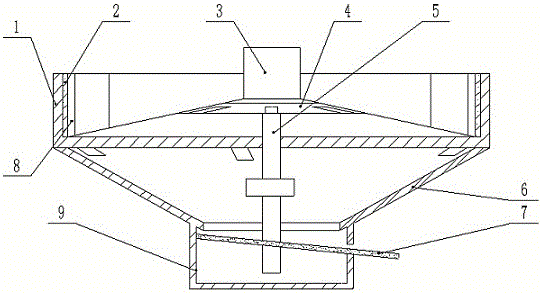
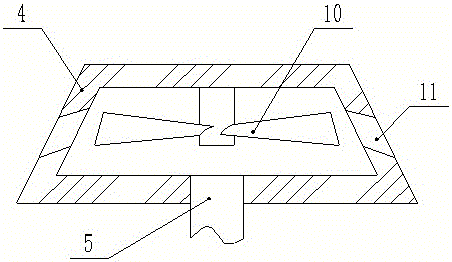
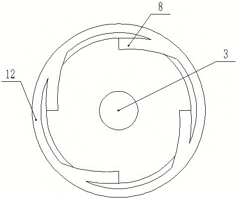
[0015] Explanation of reference numerals: quenching pool 1, magnet 2, centrifuge 3, cone 4, return pipe 5, funnel chamber 6, mesh plate 7, drain pipe 8, water tank 9, fan blade 10, drain hole 11, disc pipe 12.

[0016] Such as figure 1 The steel shot quenching collection device shown includes a quenching pool 1, a centrifuge 3 is located in the middle of the quenching pool 1, a layer of magnets 2 is provided on the inner wall of the quenching pool 1, and a funnel cavity 6 is connected to the bottom of the quenching pool 1, and the funnel cavity 6 The bottom is connected to the sink 9. The bottom of the quenching tank is provided with an upwardly protruding cone, such as figure 2 As shown, the top of the cone is rotated to install the sprinkler. The sprinkler is composed of a cone 4 and a fan blade 10. The fan blade 10 is installed on the top of the cone 4. The side wall of the cone 4 is provided with a downward sloping drain. Hole 11. The opening at the bottom of the funn...


PUM


Abstract

The invention relates to the technical field of production of steel shots, in particular to a steel shot quenching and collecting device. The device comprises a quenching bath and a funnel cavity, wherein a centrifugal machine is positioned in the middle of the quenching bath; the top of the funnel cavity is fixedly connected with the bottom of the quenching bath; a frustum which is projected upwards is arranged on the bottom surface of the quenching bath; a sprinkler capable of rotating is mounted on the top of the frustum; a layer of magnets are arranged on the inner wall of the quenching bath; the bottom of the quenching bath is connected with a plurality of water draining tubes; water inlet ends of the water draining tubes are inclined in the same direction and are attached to the inner wall of the quenching bath; water outlet ends of the water draining tubes communicate with the funnel cavity; the bottom of the funnel cavity is connected with a water tank; a discharging opening is formed in a side wall of the water tank; a screen which is inclined and is abutted to the side wall of the water tank is arranged on the discharging opening; the bottom of the water tank communicates with a return pipe; a water outlet end of the return pipe communicates with the sprinkler; and a water pump is mounted on the return pipe. By the scheme, the steel shots can be collected automatically even if the centrifugal machine works continuously, and water is recycled.

Description

technical field [0001] The invention relates to the technical field of steel shot production, in particular to a steel shot quenching collection device. Background technique [0002] Steel shot is a kind of spherical particle made of special material through special heat treatment. In the preparation process of steel shot, the equipment generally used is a centrifuge, which melts the high-carbon steel and pours it into the rotating centrifugal brick, and then relies on the centrifugal force of the centrifuge to throw out steel shots of various sizes. The discharged steel shot will fall into the quenching pool for rapid cooling to form a shot body, and finally the formed shot body will be collected for reheating and tempering, so that the shot body can reach the required hardness. Among them, in the process of collecting the pellets formed by quenching the steel shots, it is necessary to drain the water in the quenching pool first, and then collect the pellets, but because t...

Claims


Application Information

Patent Timeline
Patent Type & Authority Applications(China)
IPC IPC(8): C21D1/64C21D9/36
CPCC21D1/64C21D9/0062C21D9/36
Inventor 苏祖弟
Owner 南通壹选智能科技有限公司
Why Eureka
Try Eureka