Scratch-proof float glass conveying device

A float glass and transportation device technology, applied in glass transportation equipment, glass production, glass manufacturing equipment and other directions, can solve the problems of scratching and deformation of glass ribbon, slow gas rising speed, and late formation, etc., and achieves simple structure and improved utilization. rate, the effect of preventing scratches

Active Publication Date: 2017-05-31
SHAHE ANQUAN IND CO LTD
View PDF7 Cites 4 Cited by
  • Summary
  • Abstract
  • Description
  • Claims
  • Application Information

AI Technical Summary

Problems solved by technology

This device can protect the glass ribbon to a certain extent, but the protective layer generating device is not isolated from the outside world, so it is easy to make SO 2 A large amount of gas is released to cause environmental pollution and also cause SO 2 Gas waste while SO 2 The gas accumulates on the lower surface of the glass, and when the glass belt that has formed a protective film is driven away, it will take away part of the SO 2 Gas, but when the glass without a protective film is transported, the gas needs to rise a certain distance to react with the lower surface of the glass before it can contact the glass and react. The gas rises slowly and has no time to form during transportation. Protective film, which will still cause scratches and deformation of the glass ribbon, and in severe cases, explosion or broken plates may occur

Method used


Image

  • Scratch-proof float glass conveying device
  • Scratch-proof float glass conveying device

Examples


Embodiment Construction

[0028] The present invention will be described in further detail below by means of specific embodiments:

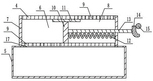
[0029] The reference signs in the accompanying drawings of the description include: tin bath part 1, transition roller table 2, annealing kiln 3, conveying roller 4, gas supply box 5, first compression chamber 6, sealing plate 7, second compression chamber 8, air hole 9. Piston plate 10, inner boss 11, spring 12, connecting rod 13, cam 14, ejector rod 15, float glass 16, supply port 17.

[0030] The embodiment is basically as attached figure 1 And attached figure 2 Shown:

[0031]The scratch-resistant float glass 16 transportation device is mainly composed of transition roller table 2 and annealing kiln 3, which are installed in turn on the right side of tin bath part 1, transition roller table 2 and annealing kiln Several transmission rollers 4 are all installed in the 3, and the transmission rollers 4 are rotatably connected on the frame. The conveying roller 4 is ...


PUM

PropertyMeasurementUnit
diameteraaaaaaaaaa

Abstract

The invention belongs to the field of glass, and particularly discloses a scratch-proof float glass conveying device. The scratch-proof float glass conveying device comprises a transitional roller table and an annealing furnace which are successively connected to one side of a molten tin bath part, wherein a plurality of conveying rollers are arranged in each of the transitional roller table and the annealing furnace; the bottom sides of the conveying rollers are rotatably connected with a gas supply box; a supply opening is formed in the top of the gas supply box; each conveying roller is hollow; sealing plates are arranged at two ends of each conveying roller; an inner boss is arranged on the inner wall of each conveying roller; each inner boss is matched with a piston plate; a first compression cavity and a second compression cavity are formed by each piston plate and the corresponding conveying roller; air holes are formed in different ends of each first compression cavity and the corresponding second compression cavity; a spring is fixed between each piston plate and the sealing plate of the corresponding second compression cavity; a connecting rod is fixed at one end of each piston plate; one end, which is away from a piston of each connecting rod is statically connected with a cam; each cam comprises projections and pits; and one side of each cam is matched with an ejector rod. By the scheme, efficiency of forming a protecting film by SO2 gas and float glass can be improved, and pollution of SO2 gas to the environment can be reduced.

Description

technical field [0001] The invention belongs to the field of glass, in particular to a device for forming float glass. Background technique [0002] At present, most of the production of float glass is to flow the molten glass into the tin bath and carry out the forming process to form a glass ribbon with a certain thickness. The glass ribbon that reaches the target thickness exits from the tin bath and passes through the transition roller of the transition roller table. Enter the annealing kiln, and complete the annealing process in the annealing kiln, and finally cut the glass ribbon into glass plates of specified size. [0003] The glass ribbon needs to be transported for a certain distance from the tin bath to the final departure from the production line. During this period, there can be as many as hundreds of conveying rollers. The direct contact between the glass ribbon and the conveying rollers may cause micro scratches on the lower surface of the glass ribbon, etc. ...

Claims


Application Information

Patent Timeline
Patent Type & Authority Applications(China)
IPC IPC(8): C03B35/16C03C17/22
CPCY02P40/57C03B35/163C03B35/166C03B35/188C03C17/22C03C2218/152
Inventor 王洪
Owner SHAHE ANQUAN IND CO LTD
Why Eureka
Try Eureka