Block machining and conveying mechanism

A conveying mechanism and block technology, applied in conveyors, transportation and packaging, etc., can solve the problems of troublesome operation, great potential safety hazards, low work efficiency, etc., and achieve the effect of simple structure, lower equipment cost, and improved production efficiency.

Inactive Publication Date: 2017-05-31
王红邓
View PDF0 Cites 0 Cited by
  • Summary
  • Abstract
  • Description
  • Claims
  • Application Information

AI Technical Summary

Problems solved by technology

However, during the pouring process of composite blocks, manual feeding is usually used, which is cumbersome to operate, has great potential safety hazards, and low work efficiency. Therefore, it is necessary to develop a composite block transportation equipment that is easy to operate and can improve efficiency.

Method used


Image

  • Block machining and conveying mechanism

Examples


Embodiment 1

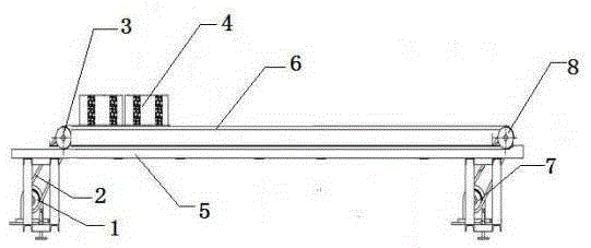
[0013] This embodiment provides a block processing and conveying mechanism, which is characterized in that: the block processing and conveying mechanism includes a left roller drive motor (1), a power transmission belt (2), a left roller (3), a block blank (4), installation frame (5), belt (6), right roller drive motor (7), right roller (8);

[0014] Among them: including the installation frame (5), the two ends of the installation frame (5) are driven to hinge the left and right rollers (3, 8), the left and right rollers (3, 8) are socketed through the belt (6), and the block blank (4) Placed on the belt (6), the left roller drive motor (1) is connected to the left roller (3) through the power transmission belt (2), and the right roller drive motor (7) is connected to the right roller through the power transmission belt (2). Roller (8).

[0015] The left and right drum drive motors (1, 7) are synchronous motors in the same direction.

[0016] The motor is a servo motor.


PUM


Abstract

The invention discloses a block machining and conveying mechanism which is characterized in that the block machining and conveying mechanism comprises a left roller driving motor, power transmission belts, a left roller, block blanks, a mounting rack, a belt, a right roller driving motor and a right roller, wherein the two ends of the mounting rack are hinged to the left roller and the right roller in a transmission manner; the left roller is in sleeving connection with the right roller through the belt; the block blanks are placed on the belt; the left roller driving motor is in transmission connection with the left roller through one power transmission belt; the right roller driving motor is in transmission connection with the right roller through the other one power transmission belt; and the left roller driving motor and the right roller driving motor are synchronous and homodromous servo motors. The block machining and conveying mechanism has the following advantages: the block machining and conveying mechanism is simple in structure, manual operation steps are reduced, the block machining and conveying mechanism is simple to operate and high in efficiency, mechanical transportation can be realized, the equipment cost is reduced effectively, and the production efficiency is improved.

Description

technical field [0001] The invention belongs to a transportation mechanism, is particularly applied to a composite block pouring machine, and particularly provides a block processing and conveying mechanism. Background technique [0002] Composite blocks mainly open several cavities on the blocks, and pour various filling materials in the cavities to meet the functionality of various blocks. For example, fill the blocks with thermal insulation materials to make composite thermal insulation concrete blocks to meet the thermal insulation requirements of the wall. For special high fireproof composite blocks, rock wool boards, glass wool boards, and expanded perlite can be used. and other inorganic materials as filling materials. However, during the pouring process of composite blocks, manual feeding is usually used, which is cumbersome to operate, has great potential safety hazards, and low work efficiency. Therefore, it is necessary to develop a composite block transportation...

Claims


Application Information

Patent Timeline
Patent Type & Authority Applications(China)
IPC IPC(8): B65G15/00
Inventor 王红邓
Owner 王红邓
Why Eureka
Try Eureka