
High speed railway safety detection system based on air-rail dual-purpose unmanned plane

A technology for safety detection and high-speed railways, applied in the field of unmanned aerial vehicles, can solve the problems of high cost, occupying normal driving space, poor flexibility, etc., and achieve the effect of low cost, high flexibility, and strong anti-interference ability

Active Publication Date: 2017-05-31
BEIJING JIAOTONG UNIV
View PDF5 Cites 14 Cited by
  • Summary
  • Abstract
  • Description
  • Claims
  • Application Information

AI Technical Summary

Problems solved by technology

[0004] In the existing method of using UAV to detect track defects, the lack of fasteners can only be detected based on the image data collected in the air, but the precise detection of cracks in rails or sleepers cannot be carried out. Man-machines can only drive on land, and cannot continuously drive along the railway track, so it cannot be applied to the precise detection of the railway track
[0005] The present invention proposes a system for high-speed railway safety detection using an air-rail dual-purpose UAV. The system utilizes two inspection methods of UAV flying in the air and running along the railroad track, taking into account the advantages of fast, flexible and high-precision detection. The flight mode is used when rapid detection of objects (such as sleeper defects and lack of rail fasteners, etc.) is required, and the rail operation mode is used when high-precision detection of objects (such as rail surface defects and early-stage diseases of sleepers) is required. Two kinds of work The mode can be flexibly arranged according to the needs of the site and switched at any time, breaking through and solving the obvious problems of the traditional ground inspection mode such as high cost, poor flexibility, and occupying normal driving space

Method used


Image

  • High speed railway safety detection system based on air-rail dual-purpose unmanned plane
  • High speed railway safety detection system based on air-rail dual-purpose unmanned plane
  • High speed railway safety detection system based on air-rail dual-purpose unmanned plane

Examples


Embodiment Construction

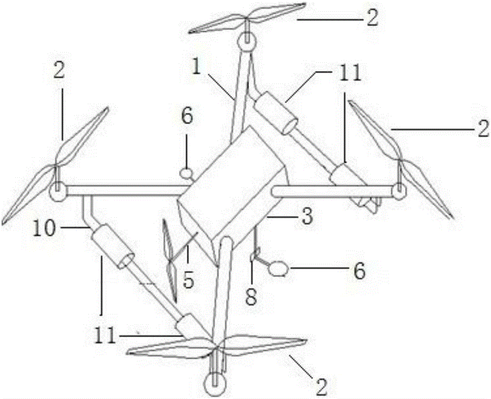
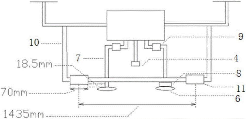
[0023] 1-body, 2-rotating blades, 3-casing, 4-high-definition camera, 5-propelling propeller, 6-horizontal guide wheel, 7-telescopic connecting rod, 8-ultrasonic rangefinder, 9-stepping motor, 10 - U-bar, 11-rolling wheels.

[0024] (1) UAV design

[0025] Classified by scale, UAVs can be divided into micro UAVs, light UAVs, small UAVs, and large UAVs. The present invention considers that the actual situation on the railway is not complicated, and its own workload is not large. Through comparative analysis, the four-rotor light UAV selected by the present invention, such as figure 1 shown. Based on the current experimental environment, some main parameters of the UAV in this scheme are listed in Table 1, such as flight height, flight time, wind resistance, etc. The UAV has a long load flight time and low vibration during flight, which is convenient for the measurement of the ultrasonic height sensor in the test, and can carry 2 kg, which can meet the experimental requiremen...


PUM


Abstract

The invention provides a high speed railway safety detection system based on an air-rail dual-purpose unmanned plane. The system comprises an unmanned plane, a remote monitoring center, an earth station, and a wireless communication module. The unmanned plane comprises rotation blades for providing flying power and propellant propellers for driving the unmanned plane to move along a rail. The earth station is used to set a flying route for the unmanned plane and control the flying mode and navigation mode of the unmanned plane in the orbit. The remote monitoring center is used to monitor the flying state of the unmanned plane, analyze the detection information, and quickly respond to the accidents during the driving process. Two routing inspection modes (namely flying in the air and moving along a rail) are adopted. Two work modes can be flexibly arranged or switched according to the actual needs. The problems of a conventional ground routing inspection mode such as high cost, bad flexibility, occupied space for normal driving, and the like, are solved.

Description

technical field [0001] The invention relates to the field of unmanned aerial vehicles, in particular to a system for high-speed railway safety detection using an air-rail dual-purpose unmanned aerial vehicle. Background technique [0002] At present, the quality inspection of my country's high-speed railway lines mainly includes manual inspection, rail inspection vehicle inspection and other means. The inspection of railway fasteners mainly relies on manual inspection. This method is time-consuming, laborious, and has poor reliability. The time for on-road inspections is insufficient. Especially with the gradual development of my country's high-speed railways, the manual inspection method has been completely unable to adapt to high-speed railways. The need for security checks. The detection of track space geometric dimension information, rail crack degree index, and train power index is mainly a combination of detection methods such as rail inspection vehicles and manual ins...

Claims


Application Information

Patent Timeline
IPC IPC(8): B64C27/08B61K9/08B61K9/10B60F5/00H04N7/18
CPCH04N7/18B61K9/08B61K9/10B64C27/08B60F5/006B60F2301/10B64U2201/20B64U2101/30
Inventor 吴云鹏秦源璟赵雪军秦勇贾利民
Owner BEIJING JIAOTONG UNIV
Learn More