
Expansion type centered clamping and milling device

A milling device and expansion technology, applied in the field of machinery, can solve the problems of affecting the processing precision, operator's hand burns, unsuitable batch processing, etc., and achieve the effects of improving efficiency, reliable work, and low cost

Inactive Publication Date: 2017-05-31
CHANGZHOU INST OF MECHATRONIC TECH
View PDF13 Cites 3 Cited by
  • Summary
  • Abstract
  • Description
  • Claims
  • Application Information

AI Technical Summary

Problems solved by technology

[0005] The milling devices that have been reported generally require manual removal of the processed workpiece
Because it will be hot after milling, if it is taken out directly, it may cause the operator's hands to be scalded, and it needs to wait for a period of time, which reduces the processing efficiency and is not suitable for batch processing.
In addition, the reported processing methods are generally manual clamping based on experience, and the clamping force used in different batches of processing is different, and the clamping force is too large or too small may affect the processing precision

Method used


Image

  • Expansion type centered clamping and milling device
  • Expansion type centered clamping and milling device
  • Expansion type centered clamping and milling device

Examples


Embodiment 1

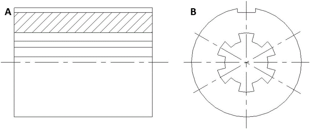
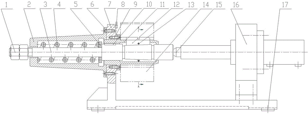
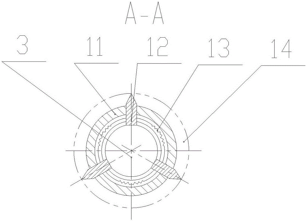
[0035] An expansion type centering and clamping milling device of the present invention is shown in figure 2 , mainly composed of locking nut 1, spring box 2, mandrel 3, return spring 4, spring seat plate 5, first screw 6, clamping body 7, tool setting block 8, second screw 9, key 10, support sleeve 11 , positioning support plate 12, shaped spring 13, top 15, pneumatic components 16 and directional keys 17 and other components.

[0036] The clamp body 7 is connected to the spring case 2 by the first screw 6 . The inner hole surface on the spring case 2 cooperates with the support sleeve 11 to realize the centering effect of the two axes. The expandable centering and clamping milling device further includes a tool setting block 8, which is installed on the upper part of the clamping body 7 at the position of the milling groove to realize the function of tool setting. The support sleeve 11 is mounted on the clamp body 7 and fixed with the second screw 9 . The support sleeve ...


PUM


Abstract

The invention discloses an expansion type centered clamping and milling device, and belongs to the technical field of machines. The expansion type centered clamping and milling device comprises a locking nut, a spring box, a mandrel, a reset spring, a spring seat plate, a clamp body, a bearing sleeve, a positioning supporting plate, a steel wire and a pneumatic assembly; the mandrel penetrates the spring box; the reset spring is mounted in the spring box, the end, pointing to the pneumatic assembly, of the reset spring is connected with the spring seat plate, the clamp body is located between the spring box and the pneumatic assembly, the bearing sleeve is mounted on the clamp body, and guide grooves which are evenly formed in the radial direction are formed in the bearing sleeve, and the positioning supporting plate is mounted in the guide grooves of the bearing sleeve; the steel wire penetrates a mounting hole in the positioning supporting plate, and the bottom circular-arc slope of the positioning supporting plate makes contact with the conical face of the mandrel. Involute spline holes are adopted in the milling device for positioning, the structure is novel and simple, cost is low, centered clamping can be achieved, and the efficiency is high; and work is reliable, and automatic upgrading and reconstruction are facilitated.

Description

[0001] Technical field: [0002] The invention relates to an expandable centering and clamping milling device, which belongs to the technical field of machinery. [0003] Background technique: [0004] The milling of workpieces in machining is usually performed by clamping the workpieces for milling. [0005] In the reported milling device, the workpiece generally needs to be manually taken out after processing. Since it will be hot after milling, if it is taken out directly, it may cause the operator's hands to be scalded, and it takes a while to wait, which reduces the processing efficiency and is not suitable for batch processing. In addition, the reported processing methods are generally manual clamping based on experience. The clamping force used in different batches of processing is different, and the clamping force is too large or too small, which may affect the machining precision. [0006] A machinery factory needs to design a milling device to process sleeve parts w...

Claims


Application Information

Patent Timeline
Patent Type & Authority Applications(China)
IPC IPC(8): B23Q3/14
CPCB23Q3/14
Inventor 苏宝莉顾惠斌刘贤锋施皓董永健
Owner CHANGZHOU INST OF MECHATRONIC TECH
Learn More