
racket automatic drilling machine

A drilling machine, fully automatic technology, applied in the direction of boring/drilling, drilling/drilling equipment, drilling templates for workpieces, etc., can solve the problem of not being suitable for large-scale industrial production and the quality of drilling is not easy Guarantee, cost a lot of labor productivity and other issues, to achieve the effect of compact structure, high drilling quality and high degree of automation

Active Publication Date: 2018-08-24
宿迁圣力佳合体育用品有限公司
View PDF12 Cites 4 Cited by
  • Summary
  • Abstract
  • Description
  • Claims
  • Application Information

AI Technical Summary

Problems solved by technology

[0002] At present, drilling machines are usually used to drill holes for the net wire holes of badminton racket frames and tennis racket frames, and the holes are manually positioned one by one to drill. The efficiency is relatively low, the positioning is not accurate enough, the drilling quality is not easy to guarantee, and it takes a lot of labor productivity, so it is not suitable for large-scale industrial production.

Method used


Image

  • racket automatic drilling machine
  • racket automatic drilling machine

Examples


Embodiment Construction

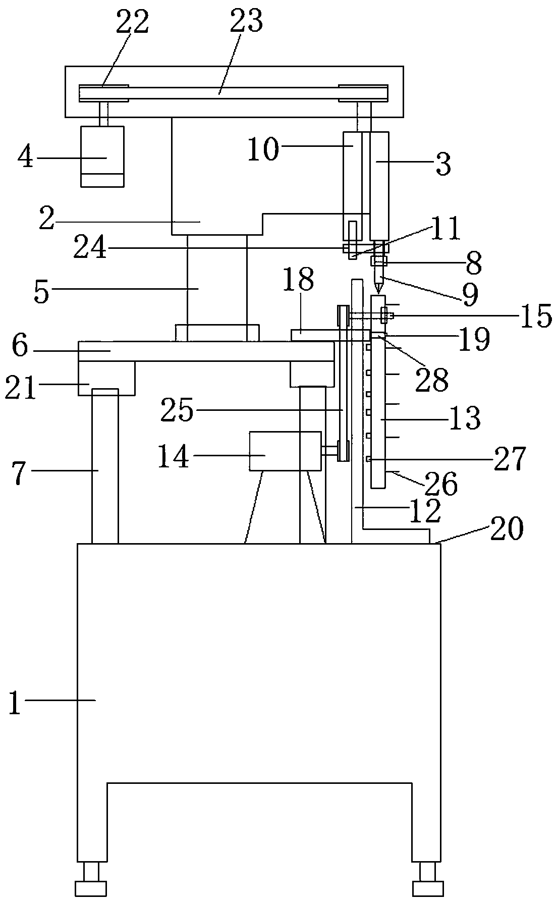
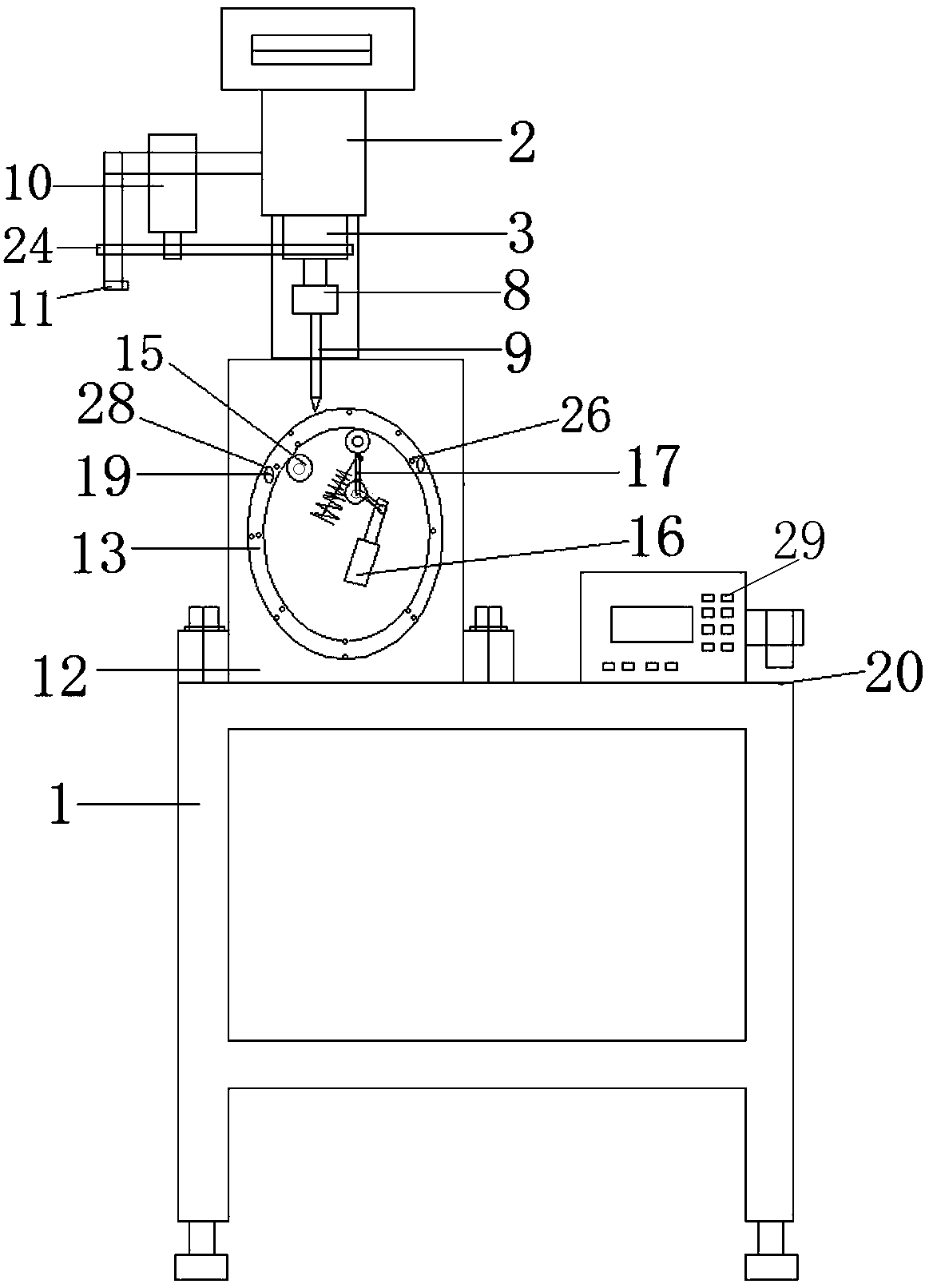
[0019] Refer to attached figure 1 , 2 , The racket automatic drilling machine includes frame 1, chassis 2, spindle 3, spindle drive motor 4, column 5, column mounting plate 6, support column 7, drill chuck 8, drill bit 9, spindle lifting cylinder 10, cylinder lifting Electromagnetic sensor 11, horizontal positioning plate 12, drilling mold 13, mold transmission motor 14, mold transmission wheel 15, mold indexing push cylinder 16, steering connecting rod 17, discharge cylinder 18 and air pressure discharge rod 19.

[0020] The top of the frame 1 is provided with a workbench 20, the cabinet 2 is installed on the top of the column 5, the column 5 is installed on the column mounting plate 6, the column mounting plate 6 is installed on the workbench 20 through four support columns 7, the column mounting plate 6 and Elastic shock-absorbing sleeve 21 is housed between the support columns 7, to eliminate vibration in the drilling process.

[0021] A main shaft transmission motor 4 i...


PUM


Abstract

The invention relates to a full-automatic drilling machine for rackets, and the automatic drilling machine is suitable for badminton racket frames and tennis racket frame net cable holes. The full-automatic drilling machine comprises a machine frame, a case, a spindle, a spindle transmission motor, a stand column, a stand column mounting plate, a supporting column, a drill chuck, a drill bit, a spindle lifting air cylinder, a lifting electromagnetic sensor, a horizontal positioning plate, a drilling die, a die transmission motor, a die transmission wheel, a die transposition pushing air cylinder, a steering connecting rod, a discharging air cylinder and an air pressure discharging rod. The spindle transmission motor is installed on one side of the case. The spindle is installed on the front portion of the case. The drill chuck is installed on the upper portion of the spindle. The drill bit is clamped by the drill chuck. The spindle lifting air cylinder is installed on the front side of the case. The front end of a piston rod of the spindle lifting air cylinder is connected with the lower end of the spindle through a connecting plate. The air cylinder lifting electromagnetic sensor is installed on the connecting plate and used for detecting the lifting position of the spindle in the drilling process. The horizontal positioning plate is installed on a workbench on the front side of the stand column mounting plate. The drill mold is installed on the outer side of the horizontal positioning plate and used for determining the installation position of a racket frame on the drilling mold.

Description

technical field [0001] The invention relates to a fully automatic racket drilling machine suitable for automatic drilling of net wire holes in badminton racket frames and tennis racket frames. Background technique [0002] At present, drilling machines are usually used to drill holes for the net wire holes of badminton racket frames and tennis racket frames, and the holes are manually positioned one by one to drill. The efficiency is relatively low, the positioning is not accurate enough, the drilling quality is not easy to guarantee, and it takes a lot of labor productivity, so it is not suitable for large-scale industrial production. Contents of the invention [0003] The object of the present invention is to provide a fully automatic racket drilling machine for the above disadvantages, which can automatically control the spindle drill under the control of the supporting microcomputer, and automatically drill holes for the racket frame installed on the drilling mold. Af...

Claims


Application Information

Patent Timeline
Patent Type & Authority Patents(China)
IPC IPC(8): B23B41/00B23B47/28B23B47/00B23Q7/00
CPCB23B41/00B23B47/00B23B47/28B23Q7/00
Inventor 蔡宜东蔡望
Owner 宿迁圣力佳合体育用品有限公司
Learn More