
Continuous type full-automatic drilling machining equipment for charger shell bodies

A technology for processing equipment and chargers, which is applied in the direction of metal processing equipment, drilling/drilling equipment, boring/drilling, etc., and can solve problems such as low work efficiency and unguaranteed drilling position accuracy

Inactive Publication Date: 2017-05-31
天长市优信电器设备有限公司
View PDF5 Cites 2 Cited by
  • Summary
  • Abstract
  • Description
  • Claims
  • Application Information

AI Technical Summary

Problems solved by technology

Traditionally, when drilling holes on the charger shell, usually first draw a dot or a cross line on the position of the charger shell where the hole needs to be drilled as a mark, then hold the charger shell and place it on the bench drill, and place the The drill bit is aligned with the marks drawn in advance to drill holes one by one. This kind of drilling method not only cannot guarantee the accuracy of the drilling position, but also has low work efficiency.

Method used


Image

  • Continuous type full-automatic drilling machining equipment for charger shell bodies
  • Continuous type full-automatic drilling machining equipment for charger shell bodies

Examples


Embodiment Construction

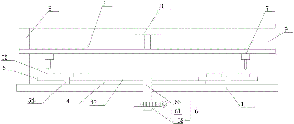
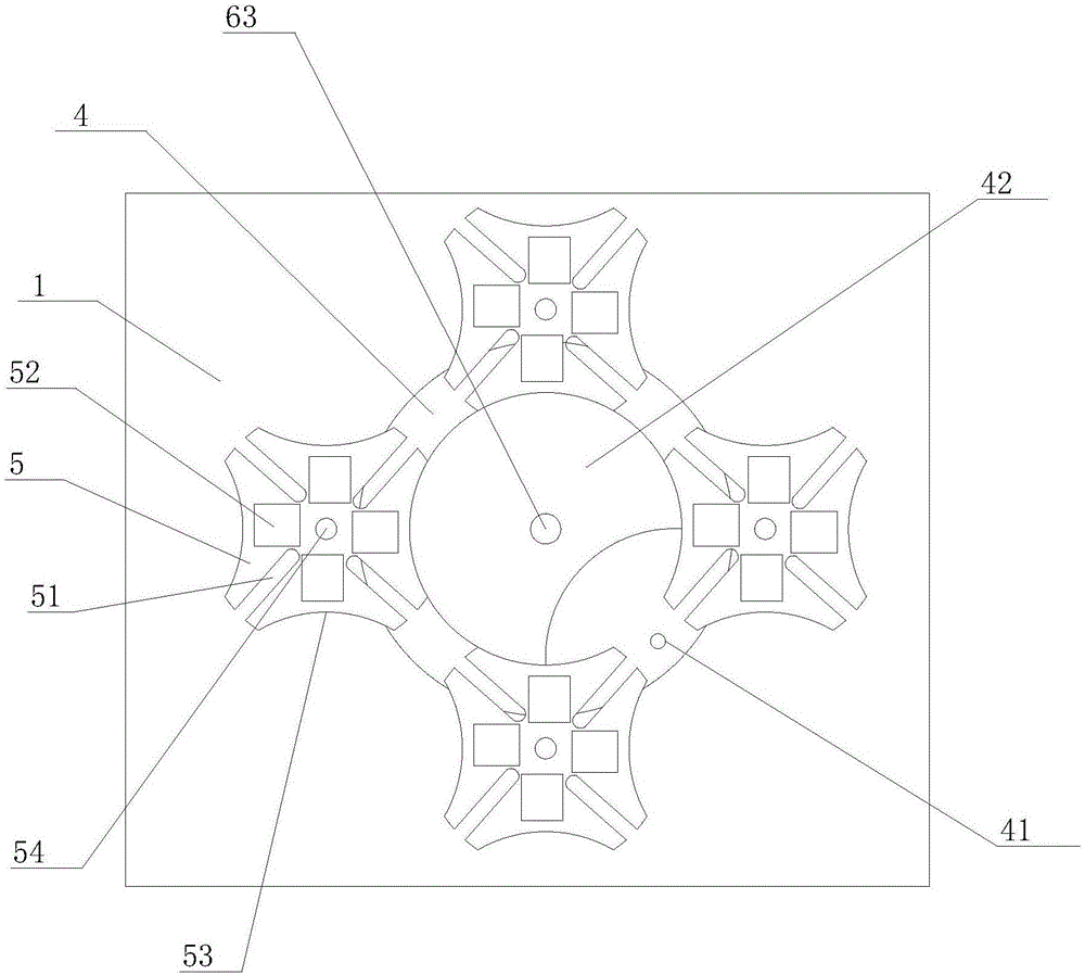
[0020] refer to figure 1 , figure 2 , the present invention proposes a continuous type charger shell automatic drilling processing equipment, including a base 1, a moving plate 2, a driving mechanism 3, a driving dial 4, N driven sheaves 5, a transmission mechanism 6, and N Drilling mechanism 7, controller, N is a natural number and N≥1, wherein:

[0021] The base 1 is arranged horizontally, the moving plate 2 is located above the base 1 and parallel to the base 1, the two ends of the base 1 are provided with a first guide column 8 and a second guide column 9, and the two ends of the moving plate 2 are respectively connected to the first guide column 8, the second guide column The two guide columns 9 are slidingly connected, and a processing area is formed between the base 1 and the moving plate 2 , and the moving plate 2 is provided with a distance measuring sensor for real-time monitoring of the distance between the moving plate 2 and the base 1 .

[0022] The driving mec...


PUM


Abstract

The invention provides continuous type full-automatic drilling machining equipment for charger shell bodies. A driving mechanism drives a movable plate to intermittently move up and down in the vertical direction. M radial grooves are formed in the peripheries of driven groove wheels. A limiting platform used for fixing a to-be-machined workpiece is arranged in the position, between every two adjacent radial grooves, of the wheel surface. The disk surface edge of a driving poking disk is provided with a cylindrical pin and a convex locking arc for locking the driven groove wheels. A concave locking arc which is matched with the convex locking arc and can enable the corresponding driven groove wheel to be static is arranged between every two adjacent radial grooves. A transmission mechanism drives the driving poking disk to intermittently rotate. Drilling mechanisms conduct drilling machining on the to-be-machined workpieces fixed to the driven groove wheels. A controller is connected with the driving mechanism, the transmission mechanism, the N drilling mechanisms and a distance measuring sensor. According to the continuous type full-automatic drilling machining equipment for the charger shell bodies, the driving mechanism, the driving poking disk, the N driven groove wheels, the transmission mechanism, the N drilling mechanisms and the controller are matched with one another, and thus end surface drilling full-automatic continuous machining work of the multiple charger shell bodies can be completed at a time.

Description

technical field [0001] The invention relates to the technical field of mechanical processing, in particular to a continuous type charger shell automatic drilling processing equipment. Background technique [0002] Now, technologies related to electric vehicles driven by using electric power, which is green energy, are rapidly developing. Most electric vehicles include an electric motor that generates rotational force, a battery that supplies electricity to the motor, an inverter that controls the RPM of the motor, a battery charger that charges the battery with electricity, and a low-voltage DC / DC converter for electric vehicles . The performance of the electric vehicle charger also has a certain influence on the use of electric vehicles. The main circuit components of the electric vehicle charger are all arranged in the casing, and the casing plays an important protective role. During the manufacturing process of the charger housing, a drilling process is often required....

Claims


Application Information

Patent Timeline
Patent Type & Authority Applications(China)
IPC IPC(8): B23B39/16
CPCB23B39/16
Inventor 董有朋
Owner 天长市优信电器设备有限公司
Learn More