
Cleaning robot suitable for photovoltaic assembly

A technology for cleaning robots and photovoltaic modules, applied in the field of cleaning robots, can solve the problems of difficult control of cleanliness, long cleaning cycle, and the need for operators, etc., and achieve the effect of saving labor costs, reducing labor intensity, and uniform cleaning force

Pending Publication Date: 2017-05-31
中新春兴新能源电力(苏州)有限公司
View PDF9 Cites 4 Cited by
  • Summary
  • Abstract
  • Description
  • Claims
  • Application Information

AI Technical Summary

Problems solved by technology

Especially the cleaning of large-matrix multi-row photovoltaic modules is difficult to clean with conventional cleaning robots
[0003] Specifically, the accumulation of dust on photovoltaic panels leads to low power generation efficiency. The greater the solar radiation of the panels, the higher the power generation of the system, and the easier it is for dust and debris in the atmosphere to adhere to the surface of the batteries, and the long-term accumulation will greatly reduce Panel Power Generation Efficiency
The existing cleaning methods include manual cleaning and mechanical cleaning. The disadvantages of manual cleaning include: 1) The cleaning cycle is long, usually once every 1-2 months; 2) The cleanliness after cleaning is difficult to control; 3) The cost is high
[0004] The disadvantages of wheeled (crawler) cleaning machines include: 1) Operators are required; 2) Cleaning operations can only be performed on flat terrain; 3) The cleaning cycle is long, usually once every 1-2 weeks; 4) The cost of use is high
[0008] Moreover, this existing scheme can only be carried out dry-cleaning, can not carry out washing
At the same time, whether it is dry cleaning or washing, there is a certain cleaning dead angle, so the cleaning effect on photovoltaic modules is not good, and it is easy to leave some traces on the surface of the modules to form shadow spots, which will affect the use of photovoltaic modules

Method used


Image

  • Cleaning robot suitable for photovoltaic assembly
  • Cleaning robot suitable for photovoltaic assembly
  • Cleaning robot suitable for photovoltaic assembly

Examples


Embodiment Construction

[0031] The specific implementation manners of the present invention will be further described in detail below in conjunction with the accompanying drawings and embodiments. The following examples are used to illustrate the present invention, but are not intended to limit the scope of the present invention.

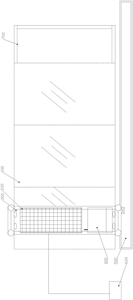
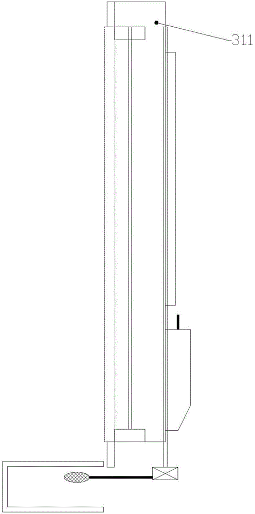
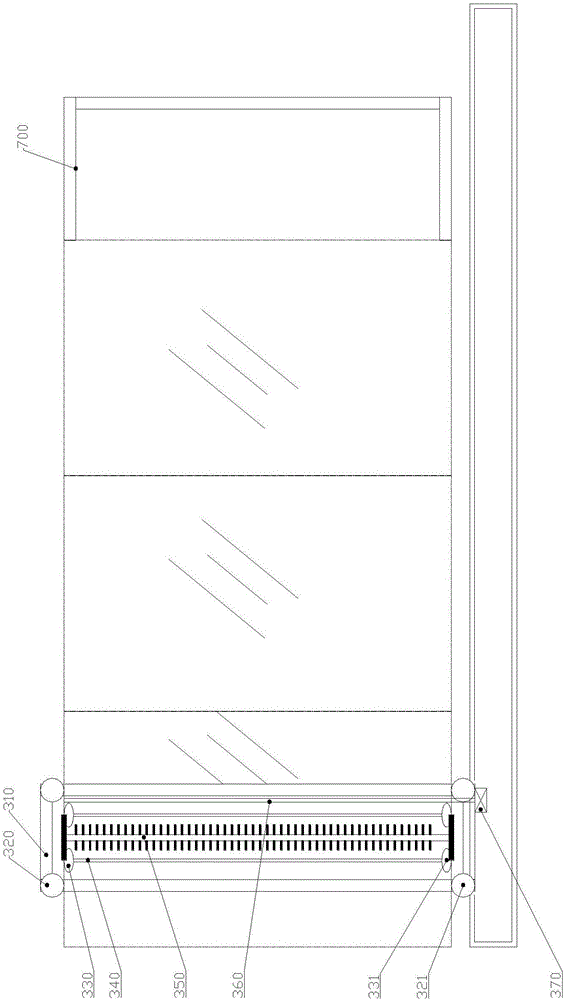
[0032] Such as Figures 1 to 4 A cleaning robot suitable for photovoltaic modules, including a robot main body 300, is different in that: in order to facilitate the installation of the robot on the photovoltaic module 100, and facilitate the robot to complete all-round cleaning and avoid cleaning dead ends, adopt The robot main body 300 includes a frame 310 on which displacement auxiliary wheels are arranged. Meanwhile, the frame 310 is also provided with a lateral displacement driving device. The present invention is provided with cleaning device in frame 310, and one side of frame 310 is provided with sump 500, and spray pipe 360 ​​is installed on frame 310, and sump 5...


PUM


Abstract

The invention relates to a cleaning robot suitable for a photovoltaic assembly. The cleaning robot comprises a robot main body. The robot main body comprises a frame. Displacement auxiliary wheels are arranged on the frame. A transverse displacement driving device is further arranged on the frame. A cleaning device is arranged in the frame. A water collecting tank is arranged on one side of the frame. A water spraying pipe is installed on the frame. The water collecting tank is connected with the water spraying pipe through a water supply assembly. A shell body is installed on the periphery of the frame, and an energy supplying assembly is arranged on the shell body. The energy supplying assembly is connected with the controlling ends of the transverse displacement driving device and the cleaning device through a controlling case. Accordingly, depending on a power supplying photovoltaic panel, self-power supplying can be achieved, and an energy storage accumulator is arranged, so that an external power supply is not needed. Intelligent remote controlling can be achieved, the cleaning robot can work at night, the operation requirement of unattended operation is met, labor cost is saved, and the labor intensity is reduced. The two modes of waterless cleaning and water cleaning can be switched.

Description

technical field [0001] The invention relates to a cleaning device, in particular to a cleaning robot suitable for photovoltaic components. Background technique [0002] Combined with the promotion and use of green energy, the development trend of the photovoltaic industry is getting better and better. The cleanliness of the surface of photovoltaic modules has a great impact on the power generation of photovoltaic systems. For the cleaning of photovoltaic modules, there is an urgent need to develop an efficient and intelligent robot. Especially the cleaning of large-matrix multi-row photovoltaic modules is difficult to clean with conventional cleaning robots. [0003] Specifically, the accumulation of dust on photovoltaic panels leads to low power generation efficiency. The greater the solar radiation of the panels, the higher the power generation of the system, and the easier it is for dust and debris in the atmosphere to adhere to the surface of the batteries, and the long...

Claims


Application Information

Patent Timeline
IPC IPC(8): B08B1/04B08B3/02B08B13/00H02S40/10H02J7/35
CPCH02J7/35H02S40/10B08B3/02B08B13/00B08B1/12B08B1/32Y02E10/50
Inventor 丁进青
Owner 中新春兴新能源电力(苏州)有限公司
Learn More