
Pneumatic straw deep-burying returning machine

A pneumatic straw technology, applied in the direction of harvesters, agricultural machinery and implements, cutters, etc., can solve the problems of plow bottom layer thickening and upward movement, soil leakage and soil moisture, excess straw, etc., to reduce the number of times of entering the field, reduce The effect of machine energy consumption and economic cost reduction

Active Publication Date: 2017-05-31
SHENYANG AGRI UNIV
View PDF7 Cites 17 Cited by
  • Summary
  • Abstract
  • Description
  • Claims
  • Application Information

AI Technical Summary

Problems solved by technology

Due to the ineffective treatment of straw, the surplus of straw is burned, causing air pollution and environmental safety issues to become increasingly prominent
At present, the technology of straw returning to the field is mainly the harvester smashing the straw back to the field, the stubble machine returning to the field, the straw returning to the field with a shallow rotation, causing the soil to leak air and moisture, and the quality of the crushed straw returning to the field is poor, and the straw cannot be used reasonably; and Long-term continuous tillage causes the soil plow layer to become shallow, and the bottom of the plow layer to thicken and move up, which affects the increase in crop yields
In the flat cropping area, the conventional plow can be used to plow 25cm to achieve straw burial, but in the northeast ridge cropping area, it is required that the seedlings are tight and the plow layer structure is loose, and the conventional plow cannot meet the requirements.

Method used


Image

  • Pneumatic straw deep-burying returning machine
  • Pneumatic straw deep-burying returning machine
  • Pneumatic straw deep-burying returning machine

Examples


Embodiment 1

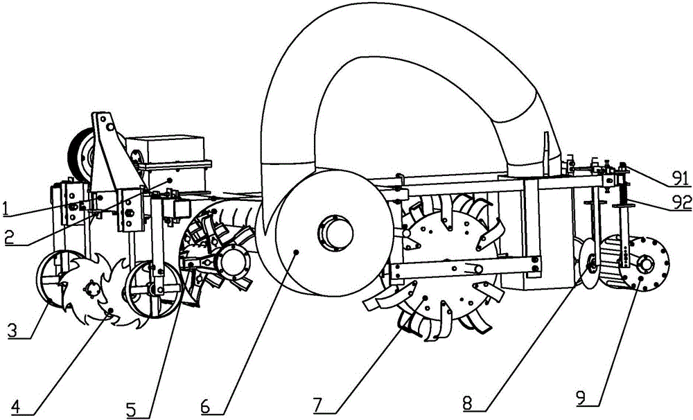
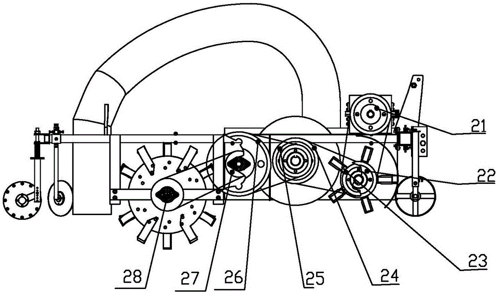
[0033] Embodiment 1: as Figure 1-Figure 2 Shown, the present invention comprises frame 1, transmission device 2 and is installed on this frame 1 and is installed on this frame 1 by the stubble breaking device 4 that advances to the rear end, picks up crushing device 5, conveying device 6, ditching device 7, soil covering device 8 and Repression device 9;

[0034] The stubble breaking disc of described stubble breaking device 4 is placed in the position of the ridge platform, and is used for breaking stubble; There are two stubble discs on the side;

[0035] like Figure 4 As shown, the picking and crushing device 5 is an existing structure, which is connected to the casing 65 of the conveying device 6, and throws straw;

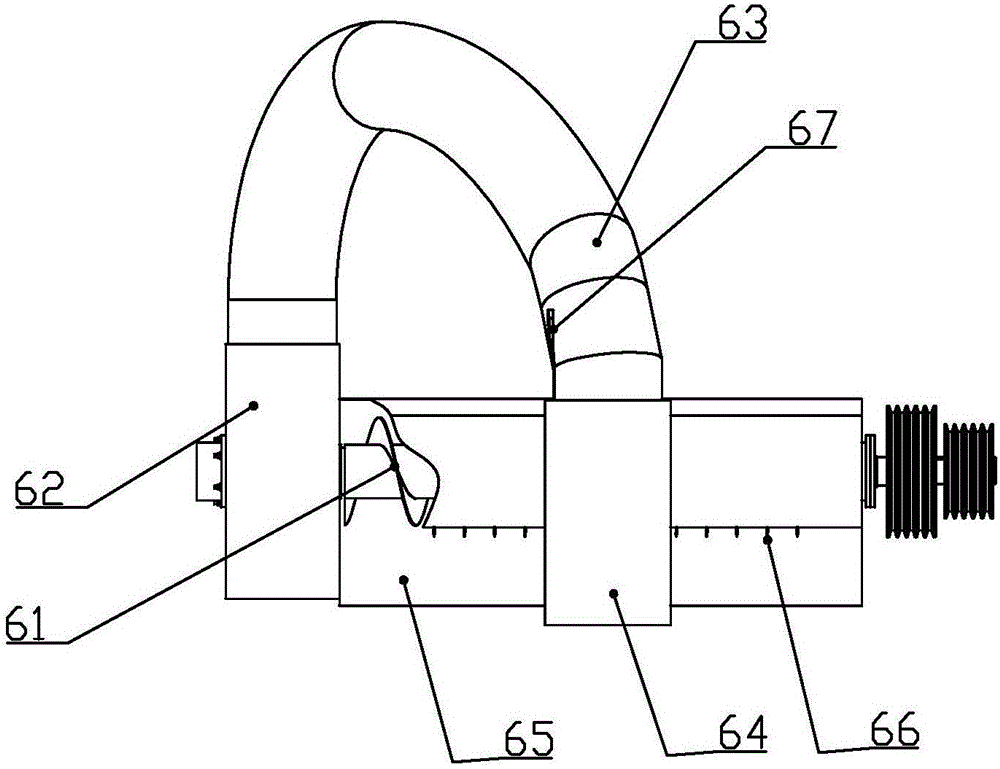
[0036] like Figure 3-Figure 5 As shown, the conveying device 6 is provided with a casing 65 at one end, through which the picking and crushing device 5 is connected to escort the crushed straw;

[0037] The conveying device 6 includes a casing 65, a bl...

Embodiment 2

[0049] Embodiment 2: The difference between this example and Embodiment 1 is that: the central angle of the casing and the matching end of the throwing knife shaft of the picking and crushing device in this example is α is 140°; the central angle of the matching end with the auger is 360°-β 270°, convey the crushed straw. The knife head gap H between the moving knife and the fixed knife is 60mm. The distance L between the knife throwing shaft of the picking and crushing device and the auger axis of the conveying device is 400-600 mm. The ditching device includes a ditching main shaft and two ditching cutter heads arranged symmetrically on the ditching main shaft, and the angle γ between the two ditching cutter heads is 10°.

Embodiment 3

[0050] Embodiment 3: The difference between this example and Embodiment 1 is that: the central angle of the casing and the matching end of the throwing knife shaft of the picking and crushing device in this example is α is 130°; the central angle of the matching end with the auger is 360°-β 260°, convey the crushed straw. The knife head gap H between the moving knife and the fixed knife is 50mm. The distance L between the knife throwing shaft of the picking and crushing device and the auger axis of the conveying device is 900 mm. The ditching device includes a ditching main shaft and two ditching cutter heads arranged symmetrically on the ditching main shaft, and the angle γ between the two ditching cutter heads is 8°.


PUM


Abstract

The invention belongs to the field of agricultural tillage and land preparation machinery, relates to a pneumatic straw deep-burying returning machine and aims to functionally realize gas-phase and solid-phase material conveying under blowing pressure and pneumatically convey crushed straws with stubble cleaned to furrows made by furrowers to realize straw deep-burying returning. The pneumatic straw deep-burying returning machine integrally and structurally comprises a frame, a transmission system, a stubble cutting device, a picking and crushing device, a conveying assembly, a furrowing device, an earthing device, a compacting device and depth rollers and the like. A pneumatic conveying device which is a key part is arranged in rear of the picking and crushing device and comprises a screw, a fan, a conveying pipeline, a discharging pipeline and the like. A furrowing device is designed and mounted under the screw and the discharging pipeline, and the compacting device, the earthing device formed by left and right earthing shovels and the like are sequentially mounted in rear of the discharging pipeline. The problem of excessive straw incineration in autumn is effectively solved, and straw deep-burying returning, soil porosity improving, soil water permeability improving, waterlogging preventing, drought resisting and soil organic matter increasing are realized.

Description

technical field [0001] The invention belongs to the technical field of agricultural machinery, in particular to a pneumatic straw deep-bury returning machine. Background technique [0002] With the improvement of crop yield, the annual output of straw is also rising. Since the straw cannot be effectively disposed of, and the excess straw is burned, the problems of air pollution and environmental safety are becoming more and more prominent. At present, the straw returning technology is mainly the harvester crushing the straw returning to the field, the stubble machine returning to the field, and the straw returning to the field with shallow rotation, which causes the soil to leak air and moisture, and the quality of the straw crushed and returned to the field is poor, and the straw cannot be used reasonably; and Long-term continuous tillage causes the soil plow layer to become shallow, and the plow bottom layer to thicken and move up, which affects the increase in crop yield...

Claims


Application Information

Patent Timeline
Patent Type & Authority Applications(China)
IPC IPC(8): A01D34/835
CPCA01D34/8355Y02P60/20
Inventor 田阳林静李宝筏宋健鹏马铁吕秋立
Owner SHENYANG AGRI UNIV
Learn More