
Inlet valve arrangement and method for external-heat engine

A technology for intake valves and engines, applied in variable displacement engines, reciprocating piston engines, valve devices, etc., can solve the problems of complex mechanical structure, space occupation, unreliable closing function of poppet valves, etc., and achieve good functional stability and wear resistance, the effect of improving efficiency

Inactive Publication Date: 2017-05-24
VIKING HEAT ENGINES AS
View PDF8 Cites 0 Cited by
  • Summary
  • Abstract
  • Description
  • Claims
  • Application Information

AI Technical Summary

Problems solved by technology

However, poppet valves have the disadvantage that they exhibit an unreliable closing function if the opening direction coincides with the direction of flow through the poppet valve and if there is a large pressure difference across the poppet valve
Many such solutions are known, but they are mechanically complex and correspondingly unreliable in terms of functionality and service life, or they lead to considerable dead volumes in the working chamber of the externally heated engine (invalid volume, dead volume)
The reason for this may be that the valve stem and other related components such as the valve guide take up a lot of space associated with the working chamber, which in turn leads to an increased dead volume as these components traditionally require additional space

Method used


Image

  • Inlet valve arrangement and method for external-heat engine
  • Inlet valve arrangement and method for external-heat engine
  • Inlet valve arrangement and method for external-heat engine

Examples


Embodiment Construction

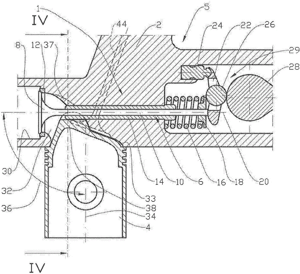
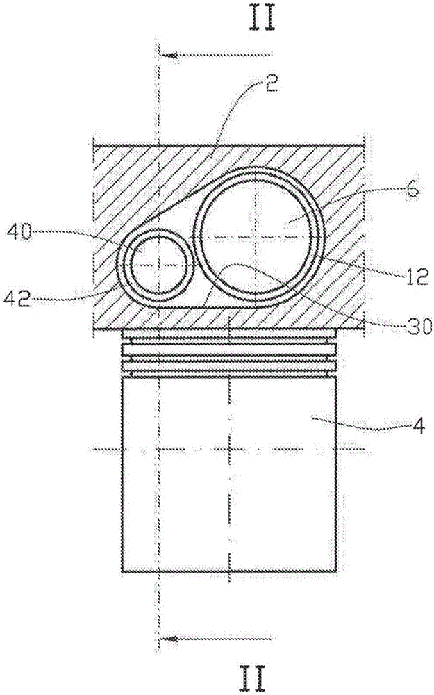
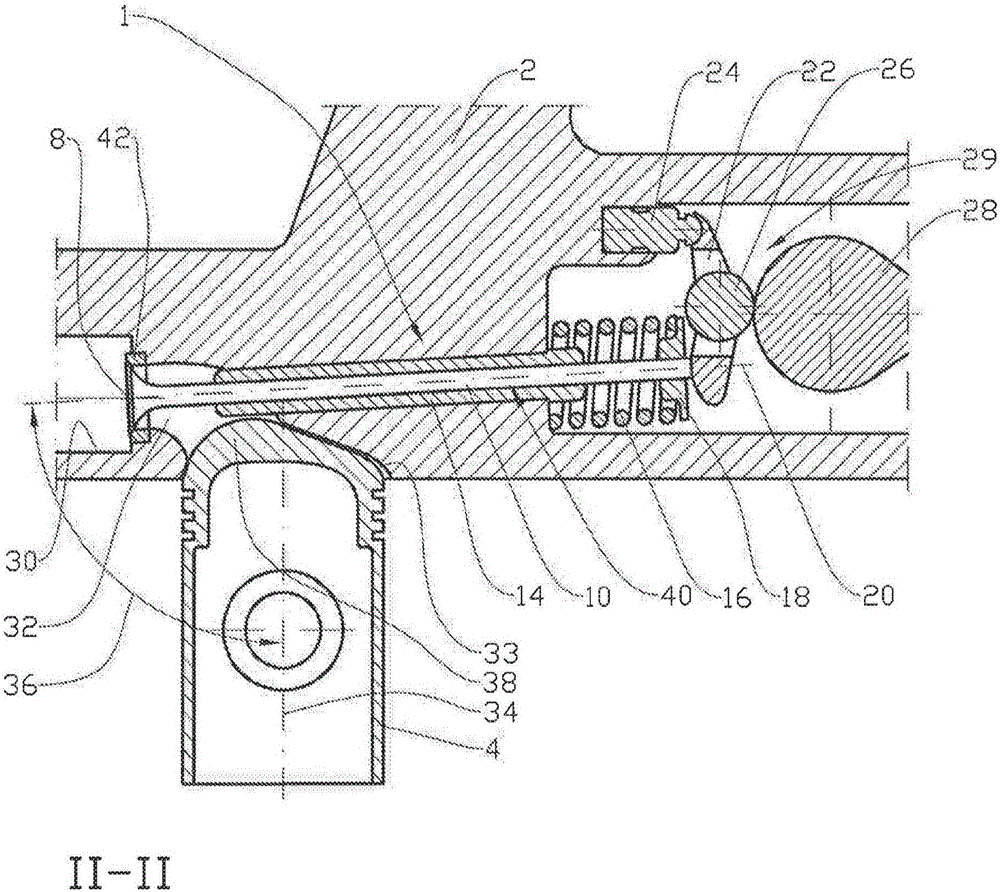
[0033] In the drawings, reference numeral 1 denotes an intake valve device located inside a cylinder head 2 . The piston 4 is shown, but the rest of those essential engine components forming part of the externally heated engine 5 are not shown. These components are known to those skilled in the art.

[0034] The intake valve arrangement 1 comprises a poppet valve 6 (its design is known per se) with a valve head (valve head) 8 and a valve stem 10, a valve seat 12, a valve guide 14 and a valve spring 16, the valve spring 16 being supported by a collar 18 is connected to the valve stem. Poppet valve 6 has a center axis 20 .

[0035] The rocker arm 22 is pivotably supported in a support piston 24 and is arranged to open the poppet valve 6 when a roller 26 within the rocker arm rests against a camshaft 28 . The components 22 to 28 constitute a valve actuator 29 .

[0036] The backing piston 24 is hydraulically operated and is arranged to maintain a desired clearance between the...


PUM


Abstract

An inlet-valve arrangement (1) for an external-heat engine (5), which includes at least one working chamber (33), each one having a cooperating piston (4) and the working chamber (33) being supplied with a working fluid via at least one controlled poppet valve (6, 40), the poppet valve (6, 40) being arranged to open in the opposite direction to the flow direction of the working fluid, and the centre axis (20) of the poppet valve (6, 40) being arranged perpendicularly within a deviation of + / -45 degrees relative to the centre axis (34) of the piston (4).

Description

technical field [0001] The present invention relates to an intake valve arrangement and method for an external-heat engine. More specifically, the present invention relates to an intake valve arrangement for an externally heated engine, comprising at least one working chamber, each working chamber having cooperating pistons, operated via at least one controlled poppet valve (provided A poppet valve) supplies working fluid to the working chamber, and the poppet valve is set to open in a direction opposite to the flow direction of the fluid. The invention also includes a method for an intake valve arrangement of an externally heated engine. Background technique [0002] Here, "externally heated engine" refers to an engine in which the working fluid has reached its operating pressure before entering a working chamber (such as an engine cylinder), for example, by heating the working fluid outside the externally heated engine, and wherein A working fluid is injected into the ex...

Claims


Application Information

Patent Timeline
Patent Type & Authority Applications(China)
IPC IPC(8): F01L1/46
CPCF01B17/022F02B33/22F01L1/185F01L1/46F01L2001/0535F01L2003/255F01L2003/258F02G1/02F01L2305/00F02B41/06F01L3/00F01L3/20F01L3/22F02F1/365F02F1/38F02F1/40
Inventor H·N·里斯拉
Owner VIKING HEAT ENGINES AS
Learn More