
Moving Magnet Speaker

A loudspeaker and moving magnet technology, applied in the direction of sensors, loudspeakers, electrical components, etc., can solve the problems of low high-frequency performance, inability to meet ultra-thin portable electronic equipment, poor high-frequency transient response, etc., to achieve Improve high-frequency performance, improve high-frequency transient response, and facilitate adjustment

Active Publication Date: 2018-12-21
GOERTEK INC
View PDF4 Cites 0 Cited by
  • Summary
  • Abstract
  • Description
  • Claims
  • Application Information

AI Technical Summary

Problems solved by technology

At present, most of the speakers used in portable electronic devices are dynamic speakers. Due to their principle, dynamic speakers have poor high-frequency transient response and low high-frequency performance, which is difficult to meet the requirements of current Hi-Fi (high-fidelity) equipment. performance requirements
At the same time, with the continuous miniaturization of portable electronic devices, speakers and vibration motors are usually packaged into one housing to form a two-in-one product to reduce the space occupied. However, when making a two-in-one product with a dynamic speaker, only It can be used as a Z-direction motor, that is, the vibration direction of the vibration motor is vertical, which will make the product thicker and cannot meet the requirements of ultra-thin portable electronic devices

Method used


Image

  • Moving Magnet Speaker
  • Moving Magnet Speaker
  • Moving Magnet Speaker

Examples


Embodiment 1

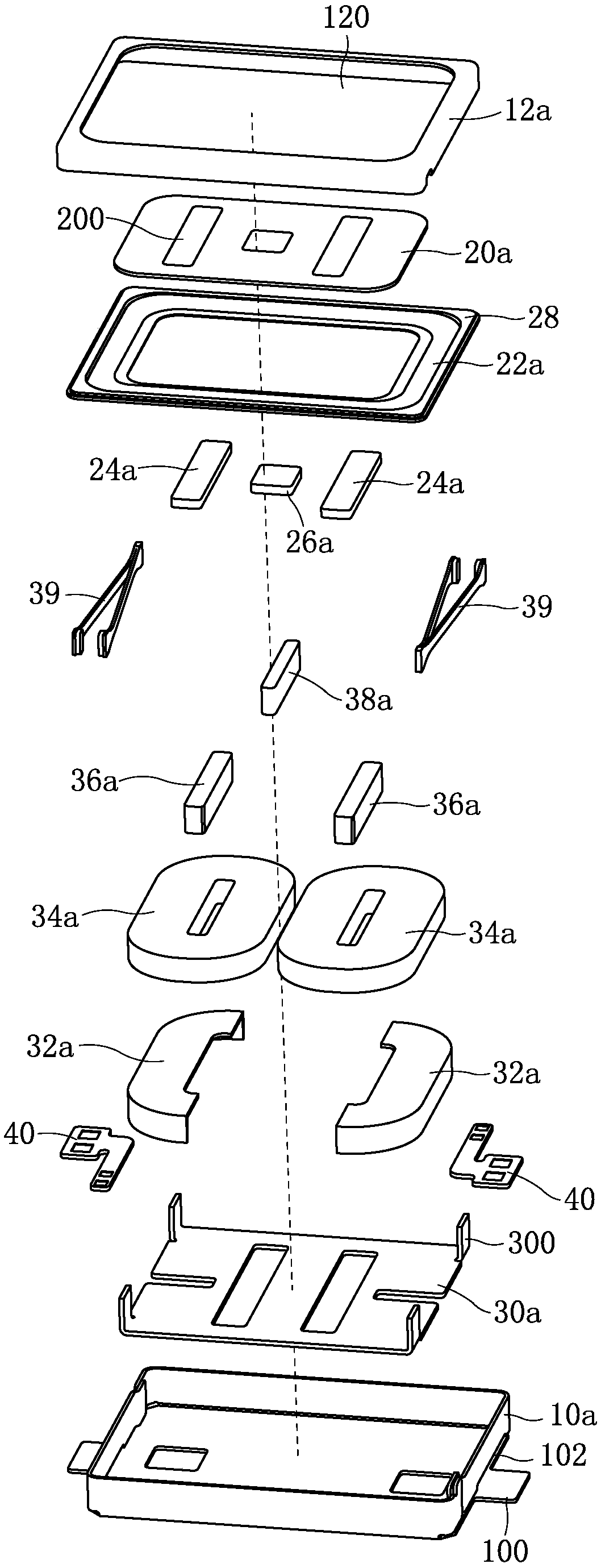
[0039] Such as figure 1 with figure 2 As shown together, a moving magnet loudspeaker has a rectangular parallelepiped structure, including a casing, a diaphragm and a vibrator accommodated in the casing, and the diaphragm and the vibrator are arranged in parallel. The casing includes a front cover 12a and a casing 10a that are combined up and down. The front cover 12a is a box-shaped structure with an open lower end, and the casing 10a is a box-shaped structure with an open upper end. The open end of the front cover 12a is fastened to the casing 10a. on the open end. The diaphragm is horizontally and fixedly installed on the front cover 12a, and the middle part of the front cover 12a is provided with a sound hole 120; It is fixedly connected with the shell 10a.

[0040] Such as figure 1 with figure 2 Commonly shown, the middle part of the diaphragm is fixed with a driving magnet 24a and a motor magnet 26a, and the positions corresponding to the driving magnet 24a and th...

Embodiment 2

[0051] This embodiment is basically the same as Embodiment 1, the difference is that:

[0052] Such as Figure 5 with Figure 6 Commonly shown, there are three driving magnets 24b, three corresponding voice coils 34b, and an armature 36b is provided in the center of each of the three voice coils 34b, and the three armatures 36b are respectively arranged corresponding to the three driving magnets 24b; The magnetization direction of the driving magnet 24b in the center is opposite to that of the two driving magnets 24b on both sides, and the current direction of the voice coil 34b in the center is opposite to that of the two voice coils 34b on both sides.

[0053] Such as Figure 5 with Figure 6 As shown together, the ring 22b is a silicone ring, which is combined with the front cover 12b and the vibrating plate 20b through an injection molding process. The vibrating plate 20b is provided with three vertical through holes 200, and the three driving magnets 24b are respective...


PUM


Abstract

Disclosed is a moving magnet-type loudspeaker, comprising a housing (12a; 10b), which housing (10a; 10b) accommodates a vibrating diaphragm and a vibrator arranged in parallel with the vibrating diaphragm, with the vibrator comprising a voice coil (34a), wherein a driving magnet (24a) is fixed on the vibrating diaphragm; the voice coil (34a) forms an electromagnet after being powered on, and generates an interactive force with the driving magnet (24a) so as to drive the vibrating diaphragm to vibrate and emit sound; a position, corresponding to the driving magnet (24a), on the vibrating diaphragm, is provided with a vertical penetrating hole (200), with the driving magnet (24a) being mounted in the vertical penetrating hole (200); a motor magnet (26a) is also fixed on the housing; the voice coil (34a) is fixed on a basket (30a), with an elastic support member (39) respectively fixed at two ends of the basket (30a),, the elastic support member (39) being provided with an elastic deformation space in a horizontal direction; and a magnetic induction line of the motor magnet (26a) cuts the voice coil (34a), thereby pushing the vibrator to vibrate in a horizontal direction. The moving magnet-type loudspeaker has a good high-frequency transient response, can conveniently adjust the vibrating space of the vibrating diaphragm, and is high in terms of space utilization rate.

Description

technical field [0001] The invention relates to the technical field of electroacoustic products, in particular to a moving magnet loudspeaker capable of realizing the functions of a loudspeaker and a linear vibration motor. Background technique [0002] The loudspeaker is an important acoustic component of portable electronic equipment. It is used to complete the conversion between electrical signals and sound signals. It is an energy conversion device; the linear vibration motor is a kind of motor and an important part of portable electronic equipment. To realize the function of vibration reminder. At present, most of the speakers used in portable electronic devices are dynamic speakers. Due to their principle, dynamic speakers have poor high-frequency transient response and low high-frequency performance, which is difficult to meet the requirements of current Hi-Fi (high-fidelity) equipment. performance requirements. At the same time, with the continuous miniaturization ...

Claims


Application Information

Patent Timeline
Patent Type & Authority Patents(China)
IPC IPC(8): H04R9/06H04R9/02
CPCH04R9/025H04R9/06H04R2400/11
Inventor 汲鹏程许超
Owner GOERTEK INC
Learn More