
A device and method for recording object motion information

A technology for object movement and moving objects, applied in the field of optics, can solve the problems of improving the camera, difficult to perform calculations, and large amount of calculation, and achieve the effect of reducing the frame rate

Active Publication Date: 2022-08-09
TSINGHUA UNIV
View PDF9 Cites 0 Cited by
  • Summary
  • Abstract
  • Description
  • Claims
  • Application Information

AI Technical Summary

Problems solved by technology

[0005] The existing scheme requires that the speed of the particles being tracked should not be too high, otherwise the frequency of photo shooting must be increased to meet the object displacement between every two frames of photos so as not to exceed the shooting range or coincide with other objects; when there are multiple measured objects in the test area or When the object to be tested has similarities with the background, it is best to have certain characteristics of the object itself that can be distinguished from the above objects, otherwise it is necessary to limit the displacement of the object between the two frames of photos to be much smaller than the distance to other objects to avoid errors, which is Further increase the shooting frequency requirements of the camera
Moreover, in order to improve the accuracy of trajectory reconstruction, the position information of the object that has been determined in the previous frames is usually used to calculate the position of the object in the next frame, which requires a lot of calculation. At the beginning of the whole process, due to insufficient historical information , it is difficult to calculate
Since optical imaging is easily affected by sensor noise, lens glare, or object surface reflection characteristics, the imaging accuracy is reduced, which in turn causes tracking interruption

Method used


Image

  • A device and method for recording object motion information
  • A device and method for recording object motion information
  • A device and method for recording object motion information

Examples


Embodiment Construction

[0027] The following describes in detail the embodiments of the present invention, examples of which are illustrated in the accompanying drawings, wherein the same or similar reference numerals refer to the same or similar elements or elements having the same or similar functions throughout. The embodiments described below with reference to the accompanying drawings are exemplary and are only used to explain the present invention, but not to be construed as a limitation of the present invention.

[0028] It will be understood by those skilled in the art that the singular forms "a", "an", "the" and "the" as used herein can include the plural forms as well, unless expressly stated otherwise. It should be further understood that the word "comprising" used in the description of the present invention refers to the presence of stated features, integers, steps, operations, elements and / or components, but does not exclude the presence or addition of one or more other features, Integer...


PUM


Abstract

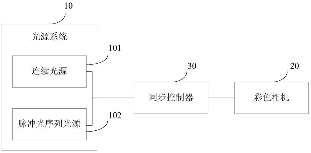
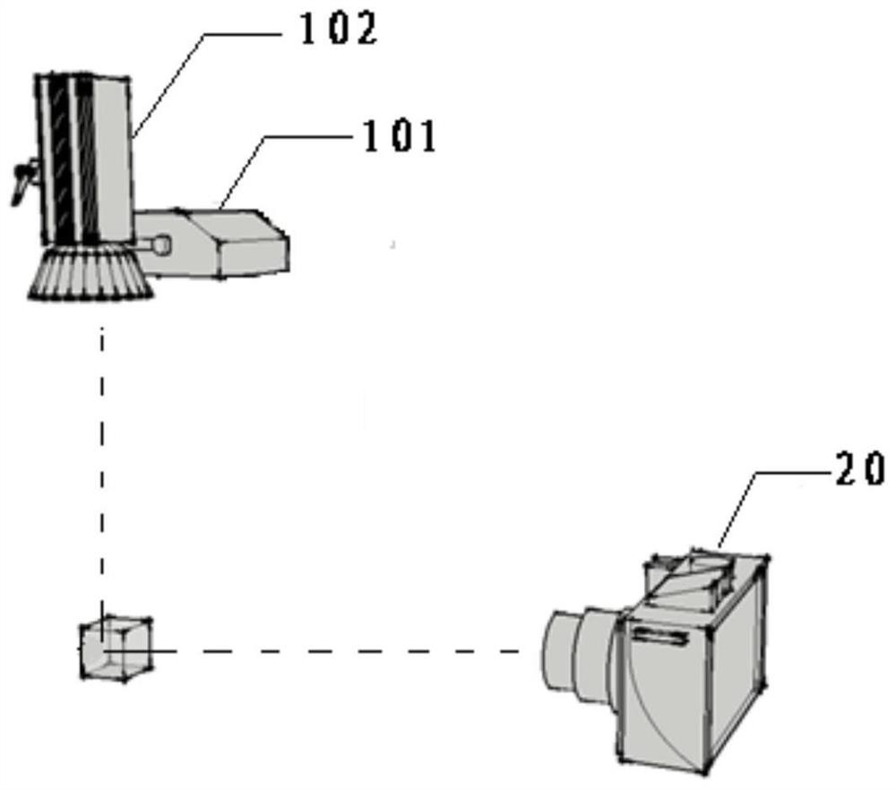
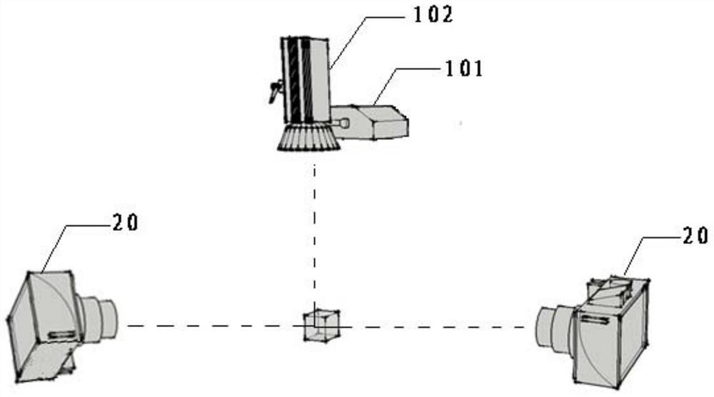
The invention provides a device and method for recording object motion information, the device includes: a light source system, a color camera and a synchronization controller; the light source system includes a continuous light source and a light source for irradiating according to a predetermined pulse flickering interval and pulse color change sequence Pulse light sequence light source; continuous light source is used to provide illumination for the test area; pulse light sequence light source is used to provide pulse light illumination for the test area; color camera is used to collect color images that record the motion trajectory of the moving object to be tested in the test area; The synchronization controller is used to control the pulsed light sequence light source and the color camera of the light source system to realize the synchronization of the pulsed light sequence light source and the color camera; wherein, the exposure time of the color camera is greater than the predetermined pulse flashing interval of the pulsed light sequence light source. The present invention can realize object motion information recording without the need for trajectory estimation and reconstruction, which saves the amount of calculation and makes the object tracking more accurate.

Description

technical field [0001] The present invention relates to the field of optical technology, in particular to a device and method for recording object motion information based on a pulsed light sequence. Background technique [0002] The tracking and measurement of moving objects is an important research direction in experimental science. The development and application of related technologies play a key role in human understanding of natural laws and utilization of natural resources. The object here can be either the object to be measured, or the tracer particles of other media or fluids. The trajectory and speed measurement of a specific object belongs to the Lagrangian tracking measurement. The existing technical means include using a high-speed camera to continuously record the position information of the object at transient time points, and then calculating its trajectory; using a radio radar to target the azimuth angle of the object Calculate and track continuous position...

Claims


Application Information

Patent Timeline
Patent Type & Authority Patents(China)
IPC IPC(8): H04N5/232H04N9/04
Inventor 李先庭王欢王宝龙石文星邵晓亮
Owner TSINGHUA UNIV
Learn More