
Strander and wire coil locking device thereof

A technology of locking device and stranding machine, which is applied in the manufacture of electrical components, circuits, cables/conductors, etc., and can solve problems such as pin bending, falling off, and large force

Active Publication Date: 2017-05-24
HEFEI SMARTER TECH GROUP CORP
View PDF6 Cites 3 Cited by
  • Summary
  • Abstract
  • Description
  • Claims
  • Application Information

AI Technical Summary

Problems solved by technology

However, if the pin hole is processed on the support shaft, the strength of the support shaft will decrease, and the problem of bending or breaking will easily occur.
Moreover, the coil acts on the pin shaft with a relatively large force, which may easily cause the pin to bend or fall off.

Method used


Image

  • Strander and wire coil locking device thereof
  • Strander and wire coil locking device thereof
  • Strander and wire coil locking device thereof

Examples


Embodiment Construction

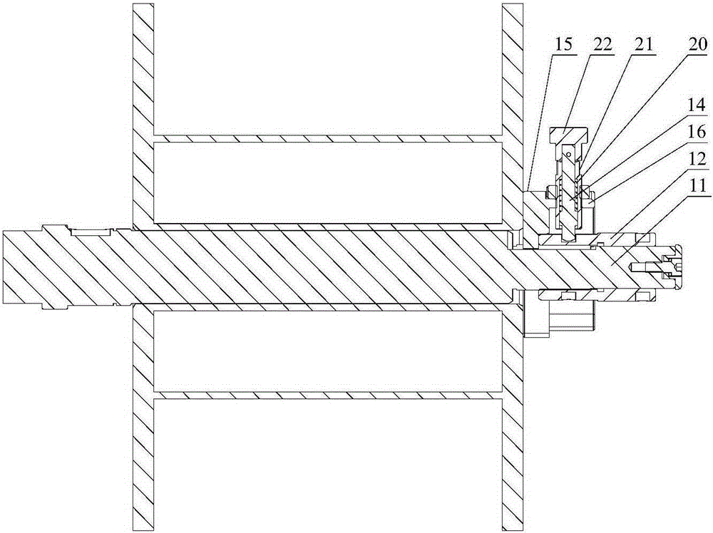
[0022] This specific embodiment provides a wire reel locking device for a wire stranding machine, which can avoid the problem of nut looseness, save time and labor when disassembling the wire reel, and is easy to operate, and avoids the problem of damage to the support shaft and positioning pin. The specific embodiment also provides a stranding machine including the above-mentioned wire drum locking device.

[0023] The following will clearly and completely describe the technical solutions in the embodiments of the present invention with reference to the accompanying drawings in the embodiments of the present invention. Obviously, the described embodiments are only some, not all, embodiments of the present invention. Based on the embodiments of the present invention, all other embodiments obtained by persons of ordinary skill in the art without making creative efforts belong to the protection scope of the present invention.

[0024] see Figure 1-Figure 4 , A coil locking dev...


PUM


Abstract

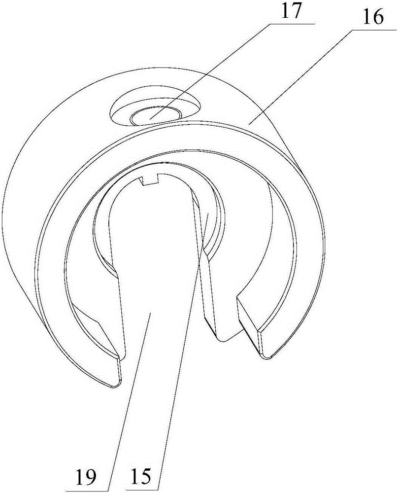
The invention discloses a strander and a wire coil locking device thereof. The wire coil locking device comprises a supporting shaft, a threaded sleeve, a positioning sleeve, a positioning pin, a nut sleeve and a handle, wherein outer thread is arranged on the supporting shaft; the inner wall of the threaded sleeve is provided with inner thread matched with the outer thread; the outer diameter of the threaded sleeve is smaller than the diameter of a center hole of the wire coil; the positioning sleeve comprises a transverse positioning end clamped between the threaded sleeve and the wire coil to stop the wire coil from moving towards the threaded sleeve direction; the positioning sleeve also comprises a radial positioning end connected with the transverse positioning end and corresponding to the outer wall of the threaded sleeve; the radial positioning end is provided with a pin hole for enabling the positioning pin to pass through; and the outer wall of the threaded sleeve is provided with a positioning hole for enabling the positioning pin to be inserted. Due to such arrangement, the wire coil locking device for the strander provided by the invention can avoid problems that the nut gets loose, disassembly of the wire coil is time-consuming and labor-consuming, the operation is convenient, and the supporting shaft and the positioning pin can be prevented from being damaged.

Description

technical field [0001] The invention relates to the technical field of cable processing, and more specifically, to a stranding machine and a coil locking device thereof. Background technique [0002] The stranding machine is used to twist multiple single wires together to form a cable. According to the way of stranding, it can generally be divided into cage type stranding machine, frame type stranding machine, tubular type stranding machine and disc type. Stranding machine etc. [0003] The stranding machine is used to wind the reels of cable auxiliary materials, such as the reels used to wind the filling rope. Due to its light weight, the reel support usually uses a support shaft to pass through the center hole of the reel. Then the wire reel is fixed on the support shaft by a locking device to prevent the wire reel from falling off. [0004] In the prior art, the locking device of the wire reel includes an external thread arranged on the support shaft and a nut matched w...

Claims


Application Information

Patent Timeline
Patent Type & Authority Applications(China)
IPC IPC(8): H01B13/02
Inventor 何金龙周章银盛卫国
Owner HEFEI SMARTER TECH GROUP CORP
Learn More