Driving circuit, liquid crystal lens, stereoscopic display device, and liquid crystal microlens
A liquid crystal lens and driving electrode technology, which is applied in the field of stereoscopic display devices, can solve the problems of time-consuming and long switching delay, etc., and achieve the effect of shortening the switching time and improving the display effect.
- Summary
- Abstract
- Description
- Claims
- Application Information
AI Technical Summary
Problems solved by technology
Method used
Image

Examples
Embodiment 1
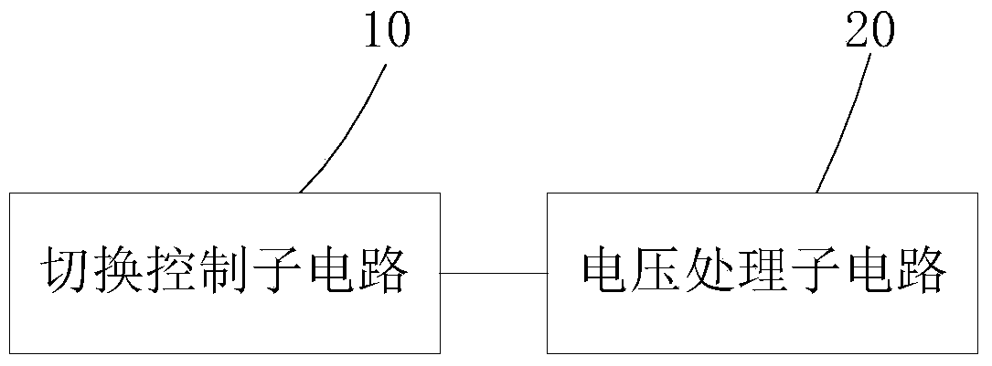
[0036] In order to solve the problem of switching delay in the switching process of the liquid crystal device, this embodiment provides a driving circuit for driving the liquid crystal device to switch the working mode of the liquid crystal device. mode provides the driving voltage required for the operation of the liquid crystal device. Such as figure 1 As shown, the driving circuit (not shown in the figure) provided by the embodiment of the present invention includes a switching control subcircuit 10 and a voltage processing subcircuit 20, wherein the switching control subcircuit 10 receives a mode switching instruction, and the mode switching instruction is used to control the liquid crystal The device switches working modes, and the mode switching instruction may be an operation instruction issued by the user, or it may be an operation instruction triggered by the liquid crystal device by detecting the working environment. This embodiment does not limit the source of the mod...
Embodiment 2
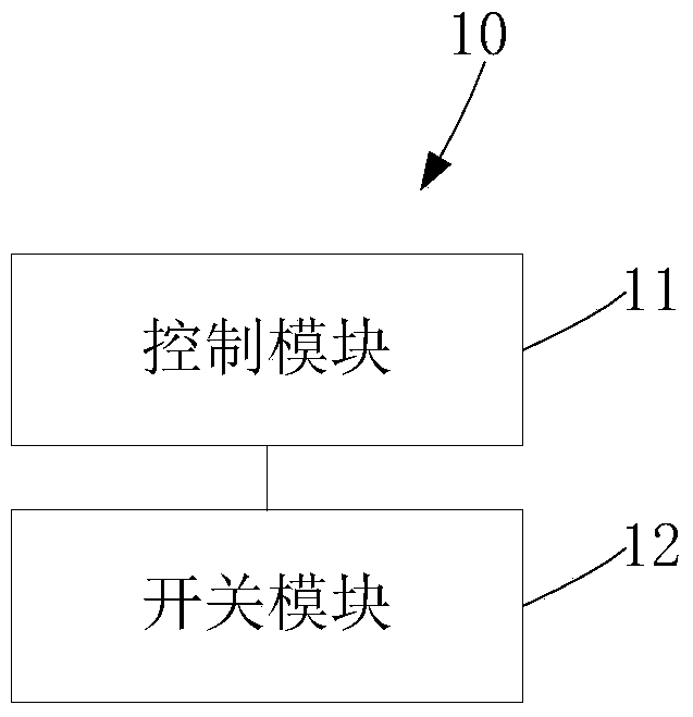
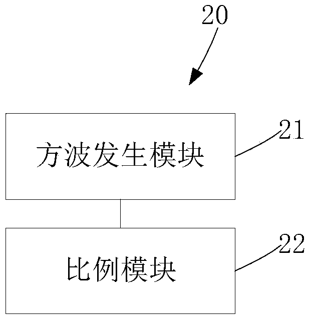
[0049] Such as figure 1 and Figure 4 As shown, the present embodiment provides a liquid crystal lens 2. The liquid crystal lens 2 includes a first substrate 21 and a second substrate 22 oppositely arranged. The first substrate 21 is provided with a plurality of driving electrodes 24, and the second substrate 22 is provided with The common electrode 25 and the liquid crystal lens 2 also include the driving circuit provided in the first embodiment. During the mode switching process, the control module 11 applies a transition voltage to the driving electrode 24 and applies a common voltage to the common electrode 25 . The liquid crystal lens 2 provided in this embodiment also includes a driving circuit. The driving circuit provided by the embodiment of the present invention includes a switching control subcircuit 10 and a voltage processing subcircuit 20, wherein the switching control subcircuit 10 receives a mode switching instruction, and the mode switching instruction is us...
Embodiment 3
[0062] Such as figure 1 , figure 2 and Figure 6 As shown, the structure of the liquid crystal lens provided in this embodiment is substantially the same as that provided in Embodiment 2. The liquid crystal lens can be a liquid crystal lens 3, and the liquid crystal lens 3 includes a first substrate 31 and a second substrate 32 oppositely arranged. The first substrate 31 and the second substrate 32 are interposed with liquid crystal molecules 33, the first substrate 31 is provided with strip-shaped driving electrodes 34, the second substrate 32 is provided with strip-shaped common electrodes 35, and two adjacent common electrodes 35 The gap therebetween forms an opening 36 . When the stereoscopic display device is used for 3D display, liquid crystal lens units L1 and L2 are formed between the first substrate 31 and the second substrate 32. The liquid crystal lens unit L1 and the liquid crystal lens unit L2 have the same structure. In this embodiment, only liquid crystal Le...
PUM
 Abstract
Description
Claims
Application Information
 - R&D
- Intellectual Property
- Life Sciences
- Materials
- Tech Scout
- Unparalleled Data Quality
- Higher Quality Content
- 60% Fewer Hallucinations
Browse by: Latest US Patents, China's latest patents, Technical Efficacy Thesaurus, Application Domain, Technology Topic, Popular Technical Reports.
© 2025 PatSnap. All rights reserved.Legal|Privacy policy|Modern Slavery Act Transparency Statement|Sitemap|About US| Contact US: help@patsnap.com