Eureka AIR delivers breakthrough ideas for toughest innovation challenges, trusted by R&D personnel around the world.

Mechanical interlocking transmission device of double power supply automatic switching switch

A technology for automatic switching of switches and transmission devices, which is applied to the power devices, electric switches, circuits and other directions inside the switch, can solve the problems of breakage of the circuit breaker handle, poor operation reliability, stuck and other problems, and achieves a small rotation angle of the motor and labor-saving operation. Also, the effect of fast switching time

Inactive Publication Date: 2008-03-19
CHANGSHU YONGXIANG ELECTROMECHANICAL
View PDF2 Cites 28 Cited by
  • Summary
  • Abstract
  • Description
  • Claims
  • Application Information

AI Technical Summary

Problems solved by technology

The mechanical interlock transmission device in the existing dual power automatic transfer switch, as disclosed in the Chinese Utility Model Patent Authorization Announcement No. CN2541941Y, is called "Mechanical Interlock Transmission Device for Dual Power Automatic Transfer Switch" and the Chinese Invention Patent Application Publication No. CN1632896A The disclosed name is "Dual Power Supply Automatic Transfer Switch Transmission Mechanism". The common problems in the above two patents are: first, since the transmission shaft and the output shaft of the geared motor are fixedly connected, when the circuit breaker is in the After the closing and opening are in place, the cam turntable fixed on the transmission shaft always exerts a certain pressure on the slider due to the resistance from the geared motor on the transmission shaft, so that the slider maintains pressure on the handle of the circuit breaker, thus It is impossible to fundamentally solve the defect that the handle of the circuit breaker is in a tight state; secondly, when the circuit breaker trips due to a fault, also due to the fixed connection between the transmission shaft and the output shaft of the geared motor, the handle of the circuit breaker is driven During the movement of the slider, it is resisted by the motor, not only will it be stuck, but also the spring in the circuit breaker will be easily damaged, and even the handle of the circuit breaker will break, which will affect the service life; moreover, when it is operated manually, Since the rotation of the drive shaft in turn will drive the geared motor to move, in order to overcome the resistance of the geared motor, manual operation becomes laborious and time-consuming
[0003] In addition, in the Chinese Utility Model Patent Authorization Notice No. CN2541941Y, which is called "Mechanical Interlocking Transmission Device for Dual Power Supply Automatic Transfer Switch", there is another problem: since the slider uses a rocker, the rocker The rod is installed on the positioning part and can rotate around the positioning part. When working, the lever principle of the rocker is used to complete the closing and opening actions of the two circuit breakers. The reliability of the action is poor, which will directly affect the switching between dual power supplies. stability

Method used


Image

  • Mechanical interlocking transmission device of double power supply automatic switching switch
  • Mechanical interlocking transmission device of double power supply automatic switching switch
  • Mechanical interlocking transmission device of double power supply automatic switching switch

Examples


Embodiment Construction

[0023] Through the applicant's description of the embodiments, it will be more helpful to understand the present invention, and make the advantages and effects of the present invention clearer. However, the embodiment does not constitute a limitation to the solution of the present invention. Any slight change in form or equivalent substitution or literal modification based on the concept of the present invention should be considered as belonging to the scope of the technical solution disclosed in the present invention. .

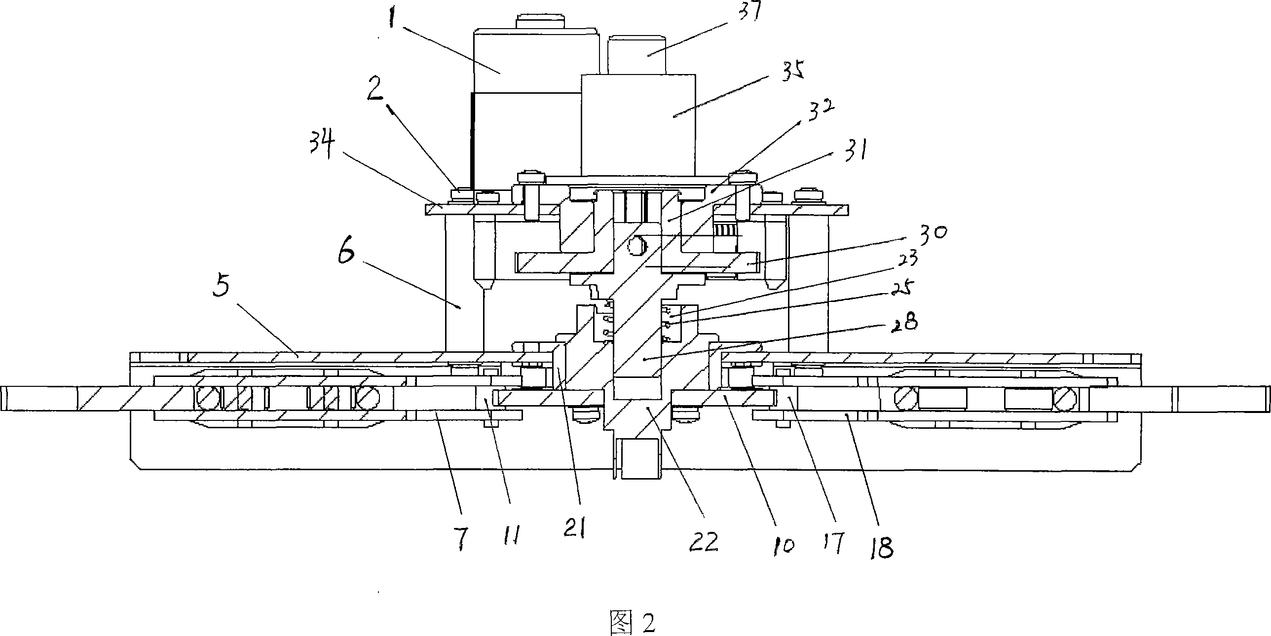
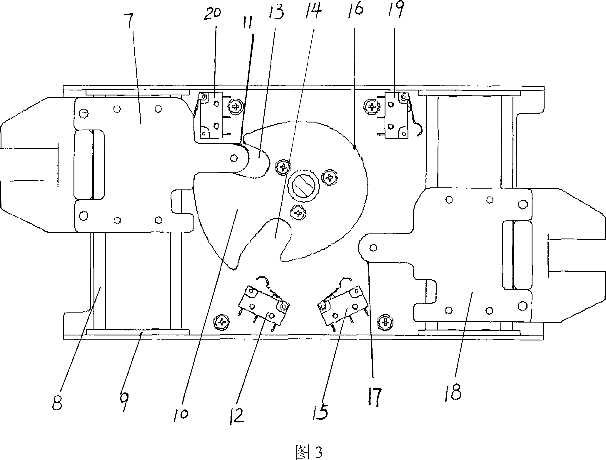
[0024] Referring to Fig. 1 and Fig. 2, the mechanical interlock transmission device of the present invention comprises an upper fixed plate 34, a motor 1, a reduction mechanism 4, a lower fixed plate 5, a transmission main shaft 22, a pair of first and second slide blocks 7, 18 and Four first, second, third, fourth microswitches 12, 15, 19, 20 and cam turntable 10, solenoid valve 35, bull gear 30, bull gear shaft 31, intermediate shaft 28. The motor 1 is in...


PUM


Abstract

A mechanical interlock transmission device for dual-power automatic transfer switches is provided, which comprises a motor, a speed reducing mechanism, upper and lower fixed plates, a transmission main shaft, first and second slippers, first, second, third and fourth micro-switches, and a cam rotary disk. The invention is characterized in that the device further comprises a solenoid valve, a main gear, a main gear shaft, and an intermediate shaft, wherein the solenoid valve is fixed below the upper fixed plate and is provided inside with a solenoid valve plug and a second return spring; the main gear is fixed below the upper fixed plate by the main gear shaft and engaged with a pinion of the speed reducing mechanism; the top end of the intermediate shaft is inserted into a gear shaft hole of the main gear shaft and the bottom end thereof is covered with a first return spring and then inserted into a central shaft hole of the transmission main shaft; the middle part of the intermediate shaft is provided additionally with a clutching toothed block seat on which a clutching toothed block is formed and engaged with a clutching toothed socket of the top of the transmission main shaft. The invention has the advantages of small motor rotation angle, short switching time, improved operational reliability of the circuit breaker, long service life, and easy manual operation.

Description

technical field [0001] The invention relates to a dual power automatic switch, more specifically a mechanical interlock transmission device for a dual power automatic switch, which is an improvement on the existing mechanical interlock transmission device for a dual power automatic switch. Background technique [0002] As we all know, the dual power supply automatic transfer switch is composed of two circuit breakers with accessories, a set of mechanical interlocking transmission mechanism driven by a single motor and a controller. The power supply is switched, and at the same time it is required that when one circuit breaker is in the closed state, the other circuit breaker is not allowed to close. It is mainly used in important places where power failure is not allowed. The mechanical interlock transmission device in the existing dual power automatic transfer switch, as disclosed in the Chinese Utility Model Patent Authorization Announcement No. CN2541941Y, is called "Mech...

Claims


Application Information

Patent Timeline
Patent Type & Authority Applications(China)
IPC IPC(8): H01H9/26H01H3/26
Inventor 方云祥唐伟
Owner CHANGSHU YONGXIANG ELECTROMECHANICAL
Why Eureka
Eureka Blog
Learn More