
Six-shaft helical bevel gear mill machining tool

A technology of spiral bevel gears and machine tools, which is applied in metal processing machinery parts, metal processing equipment, manufacturing tools, etc., can solve the problems of difficult gears to fully generate motion, difficult to ensure processing accuracy, and affecting gear processing accuracy. Light weight, high processing efficiency and good processing stability

Inactive Publication Date: 2013-01-16
天津精诚机床股份有限公司
View PDF6 Cites 6 Cited by
  • Summary
  • Abstract
  • Description
  • Claims
  • Application Information

AI Technical Summary

Problems solved by technology

However, the known driving device for the workpiece box that promotes the linkage of the B-axis mostly uses a friction wheel device. This kind of device has poor processability and is difficult to guarantee the machining accuracy. Moreover, all the weight of the workpiece box is pressed on the friction wheel, and the friction wheel is easy to slip. , unloading is more difficult, and it is difficult to ensure the full-generated motion of the gear
Moreover, the tool spindle and the workpiece spindle are all mounted on a column, and its structure not only leads to high manufacturing costs, but also poor assembly process, making it difficult to ensure machining accuracy
The rigidity of the rotary mechanism of the workpiece box of the machine tool in the prior art is difficult to guarantee, which affects the machining accuracy of the gear

Method used


Image

  • Six-shaft helical bevel gear mill machining tool
  • Six-shaft helical bevel gear mill machining tool
  • Six-shaft helical bevel gear mill machining tool

Examples


Embodiment Construction

[0030] A specific embodiment is enumerated below in conjunction with the accompanying drawings to further illustrate the present invention.

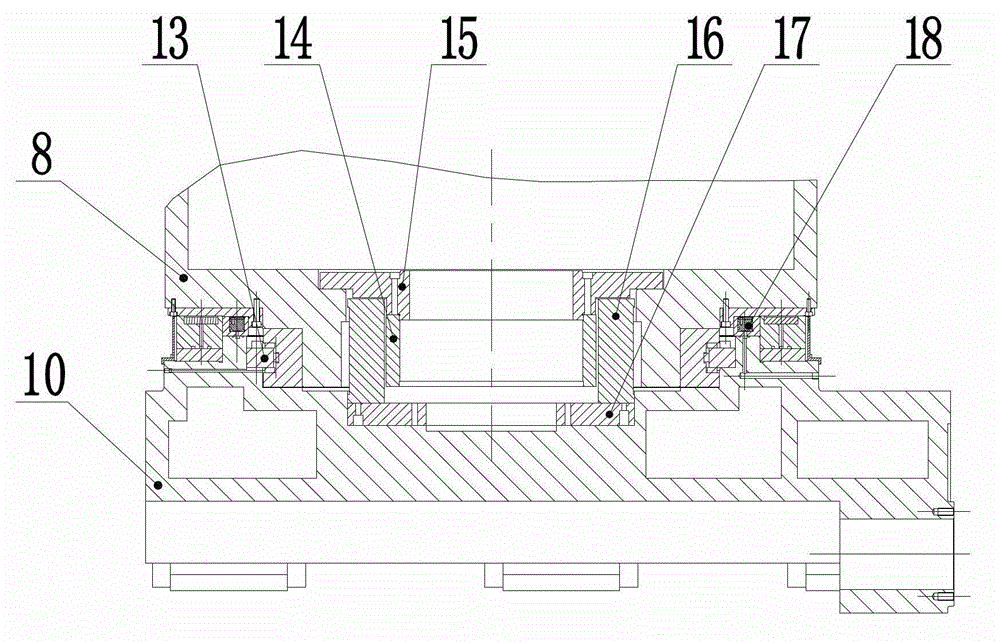
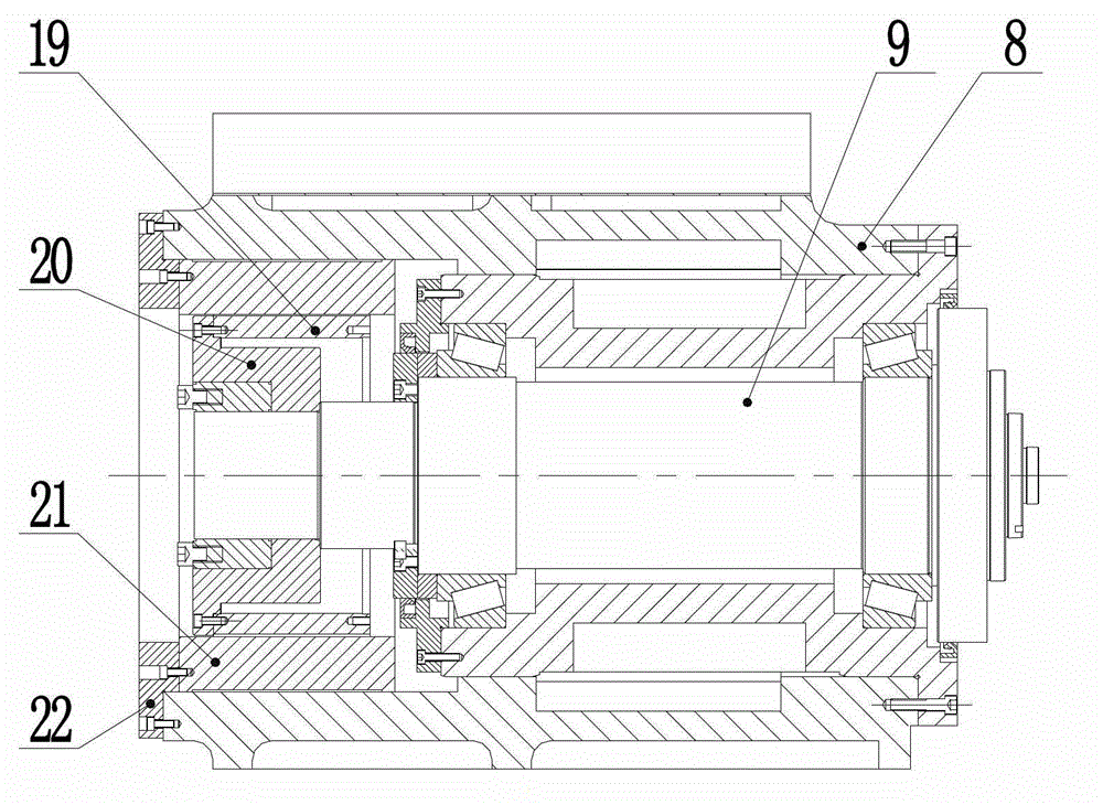
[0031] Such as figure 1 As shown, the present embodiment is a six-axis spiral bevel gear milling machine tool, including a bed 1, and a column 4 and an X-direction linear guide rail 11 are arranged on the upper end surface of the bed 1 .

[0032] The column 4 is fixedly connected to the upper surface of the bed 1, and the side of the column 4 is provided with a Y-direction linear guide rail 5, and a sliding plate 3 is connected to the Y-direction linear guide rail 5; The vertical Z-direction linear guide rail 6, the Z-direction linear guide rail 6 is slidably connected with the workpiece box 2, and the workpiece box 2 is provided with a workpiece shaft 7, the central axis of the workpiece shaft 7 is the A axis, and the workpiece is fixed on the workpiece shaft 7. The workpiece shaft 7 is rotated around the A-axis by the first drive mech...


PUM


Abstract

The invention provides a six-shaft helical bevel gear mill machining tool which comprises a tool body. A vertical column and an X-directional linear guide rail are arranged on the upper end face of the tool body, a Y-directional linear guide rail is arranged on the lateral side of the vertical column, and a sliding plate is slidably and fittingly connected to the Y-directional linear guide rail. A Z-directional linear guide rail perpendicular to the Y-directional linear guide rail is arranged on the sliding plate and slidably and fittingly connected with a workpiece box, and a workpiece is fixedly connected to a workpiece shaft which is arranged in the workpiece box. A toolbox is arranged on a tool saddle which is slidably and fittingly connected to the X-directional linear guide rail, and the tool saddle is connected with the toolbox through a rotary table bearing. A tool shaft is arranged on the side wall of the toolbox, and a tool is fixedly connected onto the tool shaft which is driven to rotate by a third driving mechanism. The six-shaft helical bevel gear mill machining tool is simple and compact in structure, convenient to assemble, fine in manufacturability, safe, reliable, short in movement stoke, low in abrasion, small in occupied area, low in cost, high in machining efficiency, high in stability, low in error and high in gear machining precision.

Description

technical field [0001] The invention relates to a gear milling machine tool, in particular to a six-axis spiral bevel gear milling machine tool. Background technique [0002] Spiral bevel gear milling machine tool is the main equipment for processing bevel gear workpieces such as automobiles and electric tools. In the prior art, the structure and adjustment of the mechanical type spiral bevel gear processing machine tool are the most complicated among the gear machine tools. With the advancement of technology, the machining of spiral bevel gears has been realized in the form of numerical control technology. Its motion model is the linkage of the tool box along the X and Y axes to simulate the rotation of the tool around the axis of the cradle, and the function of the tool tilting mechanism is changed. It is the linkage of B axis. However, the known driving device for the workpiece box that promotes the linkage of the B-axis mostly uses a friction wheel device. This kind of...

Claims


Application Information

Patent Timeline
Patent Type & Authority Applications(China)
IPC IPC(8): B23F9/08B23Q1/26B23Q5/34
Inventor 王春友霍津海魏淑英
Owner 天津精诚机床股份有限公司
Learn More