Electronic device

A technology for electronic devices and fixtures, which is applied in electrical digital data processing, digital processing power distribution, instruments, etc., and can solve problems such as large force and damage.

Inactive Publication Date: 2013-04-03
HONG FU JIN PRECISION IND (SHENZHEN) CO LTD +1
View PDF0 Cites 5 Cited by
  • Summary
  • Abstract
  • Description
  • Claims
  • Application Information

AI Technical Summary

Problems solved by technology

However, in such a method, the other end of the connector is used as the fulcrum in the process of lifting one end of the riser card, and the other end bears a large force, and the angle of rotation is too large, so it is easy to be affected by the signal riser card. Damaged by strong squeezing at the other end

Method used


Image

  • Electronic device
  • Electronic device
  • Electronic device

Examples


Embodiment Construction

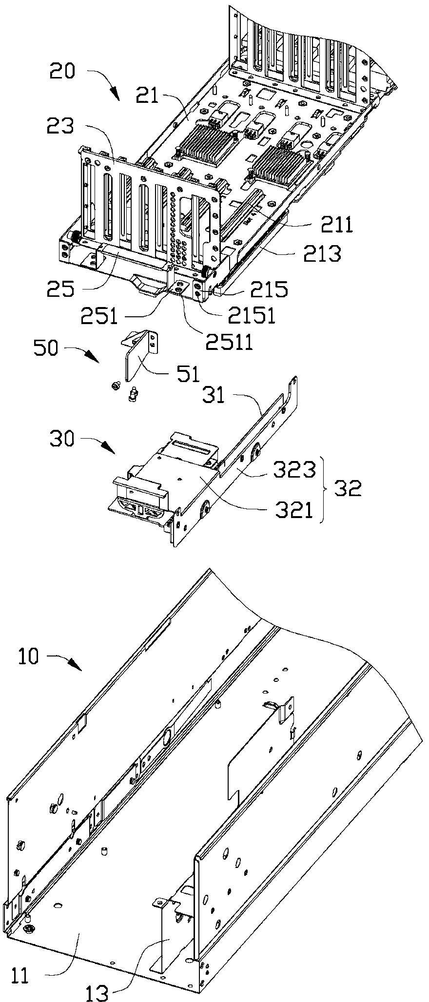
[0024] see figure 1 and figure 2 , in a preferred embodiment, an electronic device includes a case 10 , a fixing device 20 , a signal conversion module 30 and a support 50 .

[0025] The casing 10 includes a bottom plate 11 on which a circuit board (not shown) and a mounting frame 13 are installed. In one embodiment, the electronic device is a server, and the circuit board is a motherboard.

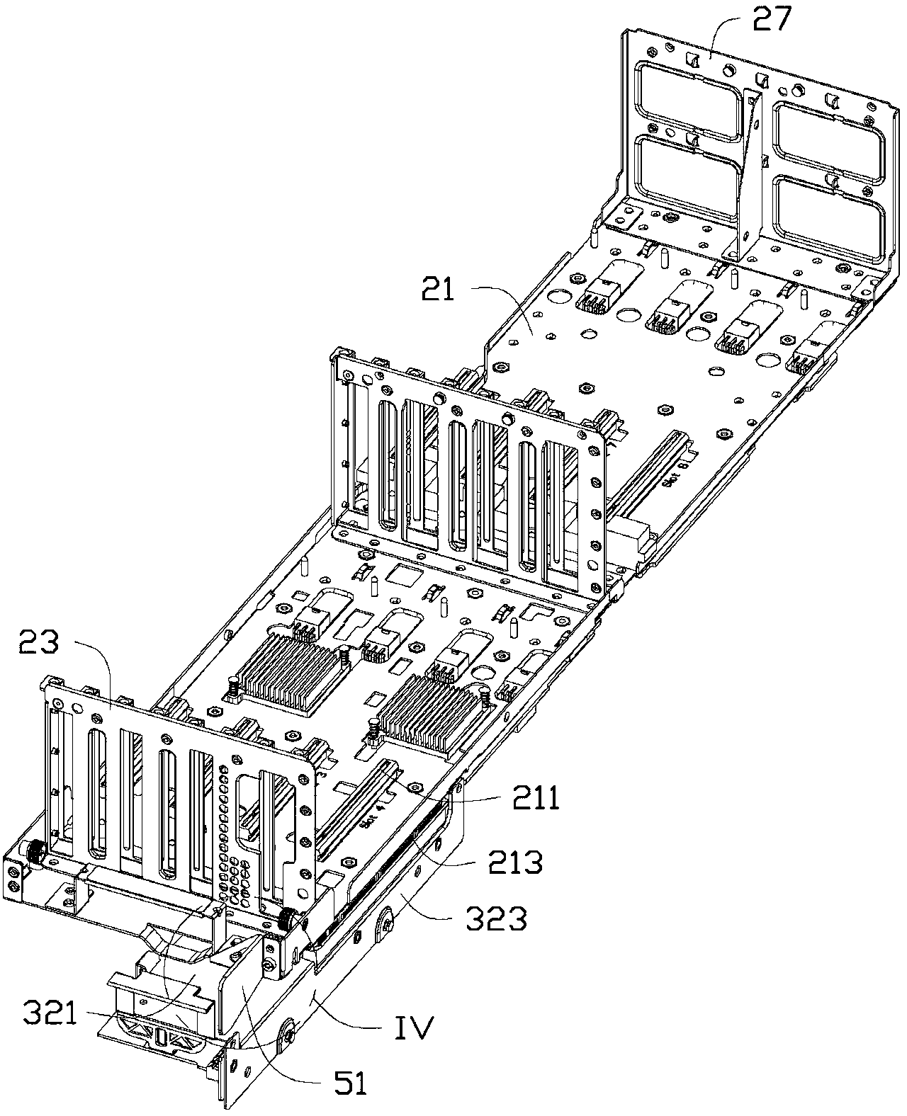
[0026] The fixing device 20 includes a circuit board 21 and a plurality of fixing frames 23 mounted on the circuit board 21 . The upper surface of the circuit board 21 is provided with a plurality of insertion slots 211 , and the lower surface of the circuit board 21 is provided with a plurality of connectors 213 . In one embodiment, the fixing device 20 is an expansion card fixing device, and several expansion cards are inserted into the insertion slots 211 and fixed on the fixing frame 23 (not shown in the figure). One end of the circuit board 21 extends a locking piece 215 upwards...


PUM


Abstract

The invention discloses an electronic device, which comprises an enclosure, a fixed device and a signal switching module, wherein the fixed device comprises a connector; the signal switching module comprises a signal card; the signal switching module and the fixed device are fixedly arranged on the enclosure; the signal card is connected onto the connector in an inserting manner; the electronic device also comprises a support piece which is fixedly arranged at one side of the fixed device and is abutted on the signal switching module; the other side of the fixed device is provided with an operation end; the connector is close to one end of the support piece and is positioned between the support piece and the operation end with an insertion point of the signal card; the operation end of the fixed device can rotate around an abutted point of the support piece and the signal switching module; and the connector is separated from the signal card in a process that the fixed device rotates around the abutted point.

Description

technical field [0001] The invention relates to an electronic device. Background technique [0002] In an electronic device that requires high display effects, such as a server, multiple graphics cards are required to support the completion. The graphics card is plugged into a riser card, the size of the riser card is approximately equal to the size of the main board of the electronic device, and is fixed on the main board in parallel. Both the mounting card and the main board are provided with a plurality of sets of connectors, and a signal transfer card is plugged between each set of connectors for connecting the transfer card and the main board. When taking out the riser card, if it is removed in parallel, the plugging force between the connector on the riser card and the signal riser card is very large, which is very laborious. Therefore, the usual way to take it out is to use the principle of leverage to lift one end of the adapter card so that one end of the connecto...

Claims


Application Information

Patent Timeline
Patent Type & Authority Applications(China)
IPC IPC(8): G06F1/18
CPCG06F1/183
Inventor 何玉伟张文达
Owner HONG FU JIN PRECISION IND (SHENZHEN) CO LTD
Why Eureka
Try Eureka