
Display device and electronic equipment

A technology for a display device and a display area, which is applied in the field of LCD, and can solve the problems of occupation, failure to achieve full display, affect the display effect and appearance of the display device, and achieve the effect of reducing power consumption

Inactive Publication Date: 2019-03-08
WUHAN TIANMA MICRO ELECTRONICS CO LTD
View PDF18 Cites 7 Cited by
  • Summary
  • Abstract
  • Description
  • Claims
  • Application Information

AI Technical Summary

Problems solved by technology

[0003] For display devices in electronic equipment, refer to figure 1 , figure 1 It is a schematic cross-sectional view of a display device in the prior art. Its edge is a non-display area that does not emit light, commonly known as black border. demand, and the black border also affects the display effect and aesthetics of the display device
[0004] In order to adapt to the development of comprehensive display, refer to figure 2 , figure 2 It is another schematic cross-sectional view of a display device in the prior art. By processing the edge area of ​​the transparent cover into a 2.5D curved surface, however, the position of the black border has not changed, and the display effect will still be affected. Moreover, the The 2.5D curved area will not display content, that is, the display device is a pseudo-full display, and it does not achieve a true comprehensive display

Method used


Image

  • Display device and electronic equipment
  • Display device and electronic equipment
  • Display device and electronic equipment

Examples


Embodiment Construction

[0075] The following will clearly and completely describe the technical solutions in the embodiments of the present invention with reference to the accompanying drawings in the embodiments of the present invention. Obviously, the described embodiments are only some, not all, embodiments of the present invention. Based on the embodiments of the present invention, all other embodiments obtained by persons of ordinary skill in the art without making creative efforts belong to the protection scope of the present invention.

[0076] In order to make the above objects, features and advantages of the present invention more comprehensible, the present invention will be further described in detail below in conjunction with the accompanying drawings and specific embodiments.

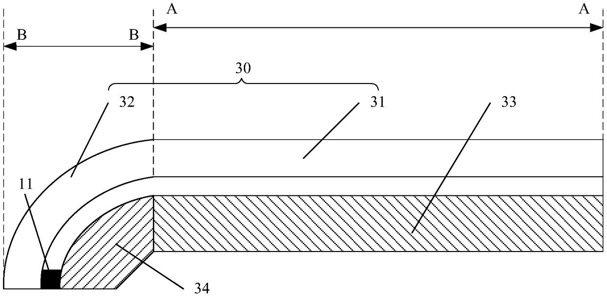
[0077] refer to image 3 , image 3 A schematic structural diagram of a display device provided in an embodiment of the present invention, the display device includes a display area AA and frame areas BB located ...


PUM


Abstract

The invention provides a display device and electronic equipment. The display device is characterized in that firstly, a transparent cover plate in a frame area is designed in a curved shape namely a3D curved shape, and comprehensibly, a black edge area is bent to the lateral side of the display device to indirectly eliminate influences of a black edge on display effects of the display device; secondly, a second display module is arranged on one side of an incidence surface of a curved transparent area of the transparent cover plate to realize 3D curved full-screen displaying; in addition, due to different display modes of a planar transparent area and the curved transparent area of the transparent cover plate, sectional displaying is realized, and power consumption of the display devicecan be effectively reduced.

Description

technical field [0001] The present invention relates to the field of LCD technology, and more specifically, to a display device and electronic equipment. Background technique [0002] With the continuous development of science and technology, various electronic devices are widely used in people's daily life and work, bringing great convenience to people's life. [0003] For display devices in electronic equipment, refer to figure 1 , figure 1 It is a schematic cross-sectional view of a display device in the prior art. Its edge is a non-display area that does not emit light, commonly known as black border. Moreover, the black border also affects the display effect and aesthetics of the display device. [0004] In order to adapt to the development of comprehensive display, refer to figure 2 , figure 2 It is another schematic cross-sectional view of a display device in the prior art. By processing the edge area of ​​the transparent cover into a 2.5D curved surface, howev...

Claims


Application Information

Patent Timeline
IPC IPC(8): G02F1/1333G02F1/13357G09G3/34
CPCG02F1/1333G02F1/133603G02F1/133615G09G3/3406
Inventor 艾有俊张洁陈志启
Owner WUHAN TIANMA MICRO ELECTRONICS CO LTD
Learn More