Stereoscopic display device detection system and detection method thereof

A technology for a stereoscopic display device and a detection system, which is applied to stereoscopic systems, televisions, electrical components, etc., can solve the problems of complex operation, crosstalk, low test efficiency, etc. Effect

Active Publication Date: 2018-03-30
SUPERD CO LTD
View PDF8 Cites 0 Cited by
  • Summary
  • Abstract
  • Description
  • Claims
  • Application Information

AI Technical Summary

Problems solved by technology

However, during the assembly process, assembly errors between the light-splitting device 11 and the display panel 12 cannot be avoided, resulting in that the light-splitting device 11 cannot be accurately attached to the display panel 12 according to the design requirements, resulting in crosstalk, poor stereoscopic display effects, and even Unable to meet stereoscopic imaging requirements and other issues
If the stereoscopic display device is not processed before leaving the factory, it will directly affect the user experience, thereby limiting the development of stereoscopic display technology
[0005] The prior art provides a liquid crystal slit grating stereoscopic display calibration method. By interrupting the first lead electrode, the initial state of each liquid crystal slit is corrected to be consistent. This stereoscopic display device calibration method is based on the liquid crystal slit grating and display However, during the lamination process, the assembly error between the liquid crystal slit grating and the display panel cannot be reduced, resulting in poor display effect of the three-dimensional display device after lamination
[0006] The prior art discloses a parameter measurement system of a stereoscopic display device. By detecting the projection image formed on the test plate when the stereoscopic display device displays a preset test picture, and analyzing the detection result, the stereoscopic display can be measured. The actual value of the grating parameters of the display device. When testing the parameter measurement system of the stereoscopic display device, the test board needs to be moved to the position corresponding to the position adjustment command. The operation is complicated, the test efficiency is low, and only the grating parameters can be obtained.

Method used


Image

  • Stereoscopic display device detection system and detection method thereof
  • Stereoscopic display device detection system and detection method thereof
  • Stereoscopic display device detection system and detection method thereof

Examples


Embodiment approach 1

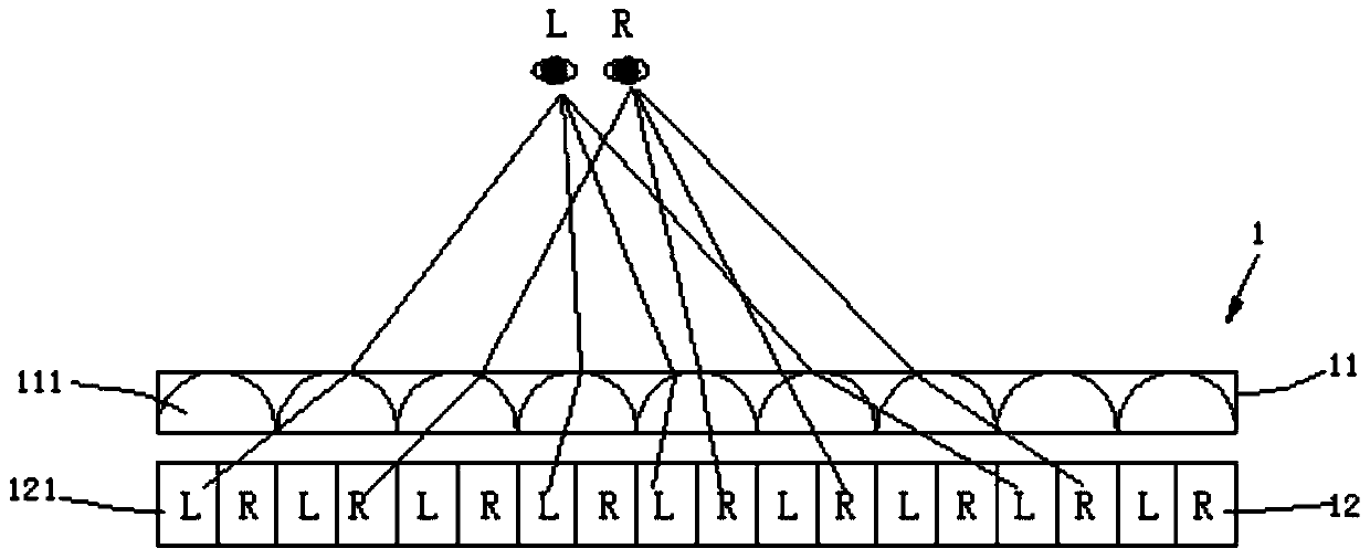
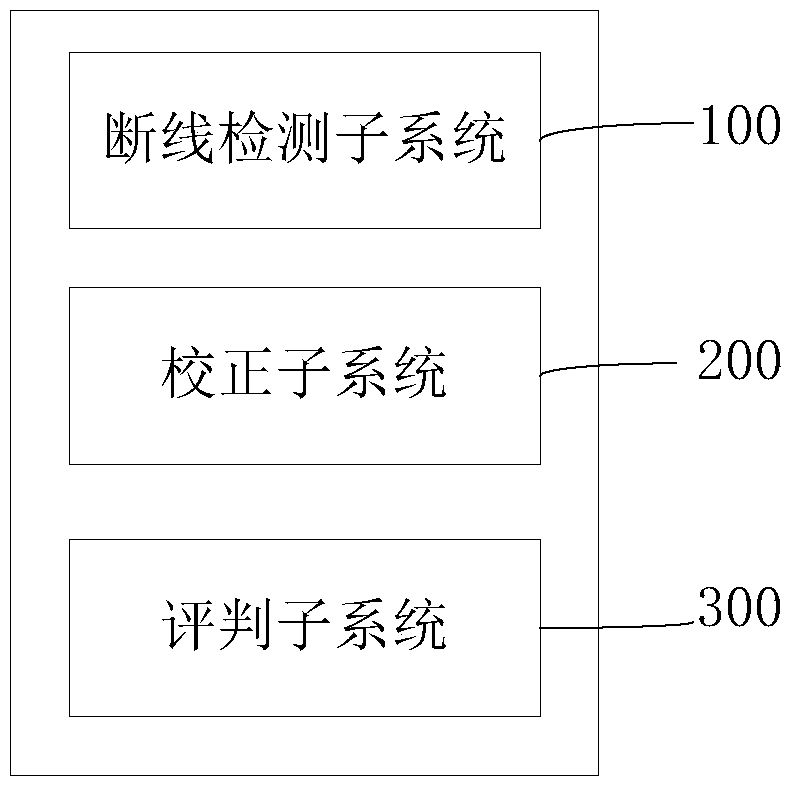
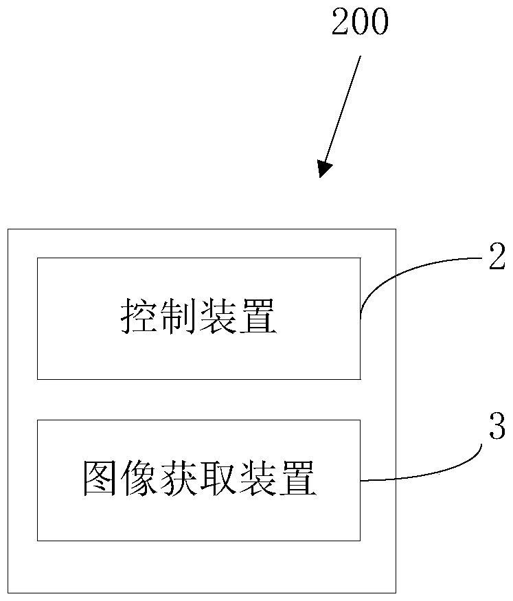
[0085] Such as figure 1 and figure 2 As shown, the detection system (not shown in the figure) provided by the embodiment of the present invention is used to detect the stereoscopic display device 1. The detection system includes a disconnection detection subsystem 100 and a calibration subsystem 200. The disconnection detection subsystem 100 The disconnection detection is performed on the stereoscopic display device 1 , and the calibration subsystem 200 obtains calibration parameters satisfying preset conditions of the stereoscopic display device 1 , and the calibration parameters are used to correct assembly errors of the stereoscopic display device 1 . The three-dimensional display device 1 includes a light-splitting device 11 and a display panel 12. If the light-splitting device 11 has a disconnection defect and is not detected, it is directly installed on the display panel 12, which will directly affect the display effect of the three-dimensional display device 1. When th...

Embodiment approach 2

[0122] The stereoscopic display device detection system provided in this embodiment has the same structure as the stereoscopic display device detection system provided in Embodiment 1, the difference is that, as figure 1 , image 3 and Figure 4 As shown, the stereoscopic display device 1 is provided with a tracking unit (not shown in the figure), and the mounting part 31 is provided with a feature mark 33 that can be recognized by the tracking unit. The tracking unit provided in this embodiment may be an infrared detection device, a tracking camera or other devices. When the tracking unit tracks the signature 33, the control device 2 controls the image acquisition device 3 to acquire a stereoscopic image. The feature identifier 33 provided in this embodiment may be a flat cardboard or a three-dimensional head portrait with features that can be recognized by the tracking unit, and details will not be repeated here. The tracking function of the tracking unit is turned on, an...

Embodiment approach 3

[0131] Such as figure 1 and Figure 10 As shown, this embodiment provides a calibration method for a stereoscopic display device, which is used to obtain a calibration parameter for a stereoscopic display device 1 that satisfies preset conditions, including the following steps:

[0132] S1, detecting whether the stereoscopic display device 1 is disconnected;

[0133] S2. If the stereoscopic display device 1 is not disconnected, acquire a correction parameter satisfying a preset condition of the stereoscopic display device 1 , and the correction parameter is used to correct an assembly error of the stereoscopic display device 1 .

[0134] The calibration parameters in this embodiment are obtained by detecting the assembled stereoscopic display device 1 to obtain the parameters corresponding to the assembly error. A stereoscopic image displayed by the stereoscopic display device 1 is acquired, and a correction parameter satisfying a preset condition is obtained according to th...


PUM


Abstract

The present invention provides a stereoscopic display device detection system that is applied to the technical field of stereoscopic display and is to detect a stereoscopic display device. The stereoscopic display device detection system includes a disconnection detection sub-system and a correction sub-system. The disconnection detection sub-system performs disconnection detection on the stereoscopic display device, and the correction sub-system obtains a correction parameter allowing the stereoscopic display device to satisfy a predetermined condition. The correction parameter is to correct an assembly error of the stereoscopic display device. The stereoscopic display device on which detection processing is performed by the stereoscopic display device detection system satisfies a shipment requirement and ensures a display quality. The present invention also provides a stereoscopic display device detection method realizing detection with respect to the stereoscopic display device, operated in a convenient manner, and having a high level of detection result reliability.

Description

technical field [0001] The invention belongs to the technical field of stereoscopic display, and in particular relates to a stereoscopic display device detection system and a stereoscopic display device detection method for detecting a stereoscopic display device. Background technique [0002] The imaging principle of stereoscopic image display technology is: based on the binocular parallax of the viewer, the left and right eyes of the viewer perceive the disparity map with image difference, and the viewer's brain forms a stereoscopic image based on the perceived image difference. [0003] Such as figure 1 As shown, the existing stereoscopic display device 1 includes a light-splitting device 11 and a display panel 12 , and the light-splitting device 11 is disposed on the light-emitting side of the display panel 12 . The display panel 11 provides a left view and a right view with image differences. Through the light splitting effect of the spectroscopic device 12, the left v...

Claims


Application Information

Patent Timeline
Patent Type & Authority Patents(China)
IPC IPC(8): H04N17/00H04N13/327
CPCH04N13/204H04N13/327
Inventor 赖敬文李统福周峰龚健
Owner SUPERD CO LTD
Why Eureka
Try Eureka