
High efficiency and energy-saving dual-axis groove type photovoltaic automatic tracking system

A high-efficiency, energy-saving, automatic tracking technology, applied in photovoltaic modules, photovoltaic power generation, photovoltaic module support structures, etc., can solve problems such as inability to use dual-axis tracking, aging accuracy of moving electrodes, structural limitations, etc.

Pending Publication Date: 2017-05-24
INST OF ADVANCED TECH UNIV OF SCI & TECH OF CHINA
View PDF10 Cites 0 Cited by
  • Summary
  • Abstract
  • Description
  • Claims
  • Application Information

AI Technical Summary

Problems solved by technology

[0002] Due to structural constraints, the existing trough-type concentrating device cannot use dual-axis tracking, but can only use single-axis or oblique single-axis tracking, and the tracking method of single-axis or oblique single-axis tracking makes it impossible to track in the north-south direction. Due to the change of latitude caused by the change of seasons throughout the year, the existing trough-type concentrating device must adopt the method of placing battery components in the north and south (that is, make the length direction of the trough-type concentrating plate in the trough-type concentrating device parallel to the north-south direction)
Although this placement method can offset or solve the change of latitude caused by the change of seasons throughout the year, there will be another problem: the tracking track of the daily sun altitude angle from east to west corresponds to the width of the trough concentrator, and due to Due to factors such as light blocking and structural cost, the battery cannot be made very wide in the same proportion. In this way, it is required to track the sun altitude angle quite frequently, otherwise the photovoltaic power generation will be lost. If the tracking frequency is too fast, it will The aging and precision wear of the accelerated movement electrode, and the instantaneous current at startup is relatively large, and the overall energy consumption increases, which is not economical

Method used


Image

  • High efficiency and energy-saving dual-axis groove type photovoltaic automatic tracking system
  • High efficiency and energy-saving dual-axis groove type photovoltaic automatic tracking system
  • High efficiency and energy-saving dual-axis groove type photovoltaic automatic tracking system

Examples


Embodiment Construction

[0022] Hereinafter, the technical solutions of the present invention will be described in detail through specific embodiments.

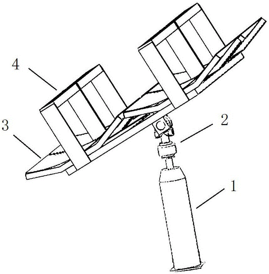
[0023] like Figure 1-4 shown, figure 1 It is a schematic structural diagram of a high-efficiency and energy-saving dual-axis slot-type photovoltaic automatic tracking system proposed by the present invention; figure 2 It is a schematic diagram corresponding to the light spot of the existing trough-type concentrator when the sun altitude angle changes during operation; image 3 It is a schematic diagram corresponding to the light spot of the tracking and concentrating cell when the sun altitude angle changes during the operation of the high-efficiency and energy-saving dual-axis slot-type photovoltaic automatic tracking system proposed by the present invention; Figure 4 It is a positional relationship diagram of the first concentrating plate and the second concentrating plate in the grooved concentrating plate in the high-efficiency and energy-sa...


PUM


Abstract

The invention discloses a high efficiency and energy-saving dual-axis groove type photovoltaic automatic tracking system. The system comprises a groove type condensation component and a dual-axis tracking device. The groove type condensation component comprises a groove type condensation plate and a groove type condensation battery. The groove type condensation plate is provided with a condensation groove. The groove type condensation battery is a bar-shaped battery with a length direction. The groove type condensation battery is located above the condensation groove and is fixed. The length direction of the groove type condensation battery is consistent with the extending direction of the condensation groove. The groove type condensation component is arranged on the dual-axis tracking device, and the length direction of the groove type condensation battery is arranged in the east-west direction. The dual-axis tracking device is used to track the change of the azimuth and the height angle of the sun and control the orientation change of the groove type condensation component according to the change of the azimuth and the height angle of the sun. According to the invention, the number of times of solar tracking is effectively reduced; the frequency of start and stop of a motor is reduced; and the requirement for tracking accuracy is reduced.

Description

technical field [0001] The invention relates to the technical field of solar energy automatic tracking, in particular to a high-efficiency and energy-saving dual-axis slot-type photovoltaic automatic tracking system. Background technique [0002] Due to the structural limitation of the existing trough concentrator, dual-axis tracking cannot be used, and only single-axis or oblique single-axis tracking can be used. Due to the latitude changes brought about by changes in the four seasons of the year, the existing trough type concentrator must adopt the method of placing the battery components in the north and south (ie: the length direction of the trough type concentrator in the trough type concentrator is parallel to the north-south direction). Although this placement method can offset or solve the latitude changes caused by changes in the four seasons of the year, there will be another problem: the daily sun altitude angle from east to west tracking trajectory corresponds to...

Claims


Application Information

Patent Timeline
IPC IPC(8): G05D3/12H02S20/32
CPCH02S20/32G05D3/12Y02E10/50
Inventor 欧浪情
Owner INST OF ADVANCED TECH UNIV OF SCI & TECH OF CHINA
Learn More