
A Transformation and Update Method of Sonar Fan Diagram

An updating method and fanning technology, applied to radio wave measurement systems, instruments, etc., can solve the problems of consuming hardware resources, reducing memory capacity requirements, and increasing calculation time, so as to avoid trigonometric or inverse trigonometric function transformation and improve computing efficiency And the effect of accuracy and fast conversion

Active Publication Date: 2019-06-07
江苏中海达海洋信息技术有限公司
View PDF6 Cites 0 Cited by
  • Summary
  • Abstract
  • Description
  • Claims
  • Application Information

AI Technical Summary

Problems solved by technology

The first one: use the idea of ​​exchanging space for time, store the value of the trigonometric function in the hardware memory in advance, and call it directly when needed, Chen Jingyu [Chen Jingyu, high-resolution radar display coordinate transformation and related design, ship electronic countermeasures, 2001 】Using the periodicity and symmetry of trigonometric functions, EPROM stores the carry value of the first quadrant, thereby reducing the capacity requirement of the memory
However, it still needs to consume hardware resources for storage, and some system configurations cannot meet the requirements; the second type: the idea of ​​using time for space, using iterative approximation algorithm to calculate trigonometric function values, but it will increase the number of iterations, resulting in an increase in calculation time For example, Tan Yiyu et al. [Tan Yiyu, Bian Wenbing, A Coordinate Transformation Circuit Based on CORDIC Algorithm, Data Acquisition and Processing, 2001] used the coordinate transformation circuit of CORDIC algorithm to realize the transformation of B-ultrasound images. data quantization bits to ensure accuracy

Method used


Image

  • A Transformation and Update Method of Sonar Fan Diagram
  • A Transformation and Update Method of Sonar Fan Diagram
  • A Transformation and Update Method of Sonar Fan Diagram

Examples


Embodiment Construction

[0040] In order to make the object, technical solution and advantages of the present invention more clear, the present invention will be further described in detail below in conjunction with the accompanying drawings and embodiments. It should be noted that the drawings are only for illustrative purposes and are not drawn to a strict scale, and there may be partial enlargements and reductions for the convenience of description, and there may be certain omissions for some known structures.

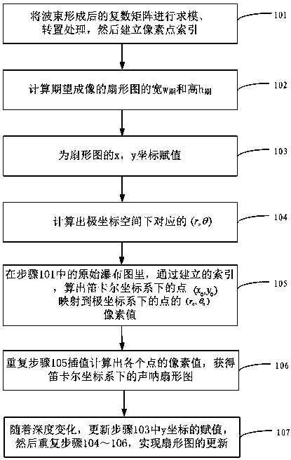
[0041] figure 1 It is a diagram of an embodiment of the method for converting and updating the sonar sector diagram of the present invention.

[0042] Such as figure 1 As shown, the present invention provides a method for converting and updating a sonar sector diagram. The method mainly includes the following steps:

[0043]In step 101, the beamformed complex matrix is ​​subjected to modulo calculation and transposition processing, and then a pixel point index is established, where a pix...


PUM


Abstract

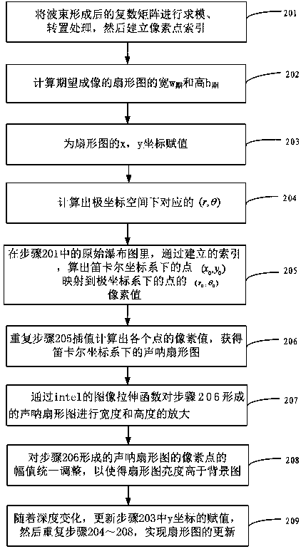
The invention provides a conversion updating method for a sonar sector diagram. The method comprises the steps: a, carrying out the module solving and transposition of a complex matrix after a wave beam is formed, and building a pixel index; b, calculating a wide w period and a high h period of a sector diagram of expected imaging; c, assigning values to x and y coordinates of the sector diagram; d, calculating the corresponding (r, theta) in a polar coordinates space; e, solving a pixel value of a point (x0, y0) in a Cartesian coordinate system mapped to a point (r0, theta 0) in a polar coordinate system in an original waterfall plot at step a through the built index; f, repeatedly carrying out the step d, carrying out the interpolation calculation of pixel values of all points, and obtaining a sonar image in the Cartesian coordinate system; g, updating the assigned values of y coordinates with the changing of depth, then repeatedly carrying out the steps d-f, and achieving the updating of the sector diagram. According to the invention, an upper computer is used for building the index and the interpolation, and the method avoids the tedious trigonometric or inverse trigonometric function conversion of an FPGA, improves the calculation efficiency and accuracy, and saves the time.

Description

technical field [0001] The invention belongs to the field of sonar image processing, and mainly relates to the rapid conversion from a waterfall diagram to a sector diagram in the test process and real-time dynamic update. Background technique [0002] Multi-beam sounding mainly uses the receiving transducer to receive the echo signal scattered by the seabed from the acoustic wave emitted by the transmitting transducer, and then after data processing, the seabed information of the scanning area is presented on the host computer. In the process of displaying the sonar image, the data after beamforming is a complex number array under (r, θ) coordinates. Since the data is in the polar coordinate space, if the direct imaging display does not conform to the visual habits of the human eye, it is necessary to convert the polar coordinates to The waterfall diagram below is converted into a fan diagram of (x, y) in Cartesian coordinates, and then displayed on the host computer interf...

Claims


Application Information

Patent Timeline
Patent Type & Authority Patents(China)
IPC IPC(8): G01S7/52
CPCG01S7/52
Inventor 常小磊刘冲罗宇陈君
Owner 江苏中海达海洋信息技术有限公司
Learn More