
A wire loss detection device

A detection device and wire technology, applied in the direction of measuring devices, measuring angles, fault locations, etc., can solve problems such as potential safety hazards and irregularities, and achieve the effect of compact device design and easy portability

Active Publication Date: 2019-02-19
JINAN CITY CHANGQING DISTRICT POWER SUPPLY CO OF STATE GRID SHANDONG ELECTRIC POWER CO +1
View PDF7 Cites 1 Cited by
  • Summary
  • Abstract
  • Description
  • Claims
  • Application Information

AI Technical Summary

Problems solved by technology

In real life, due to irregular operation, there are many potential safety hazards. For example, replacing high-cost wires with low-cost wires will cause problems if the current is too large.

Method used


Image

  • A wire loss detection device
  • A wire loss detection device
  • A wire loss detection device

Examples


Embodiment Construction

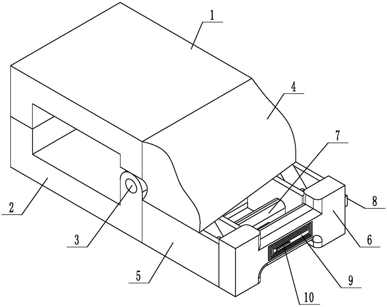
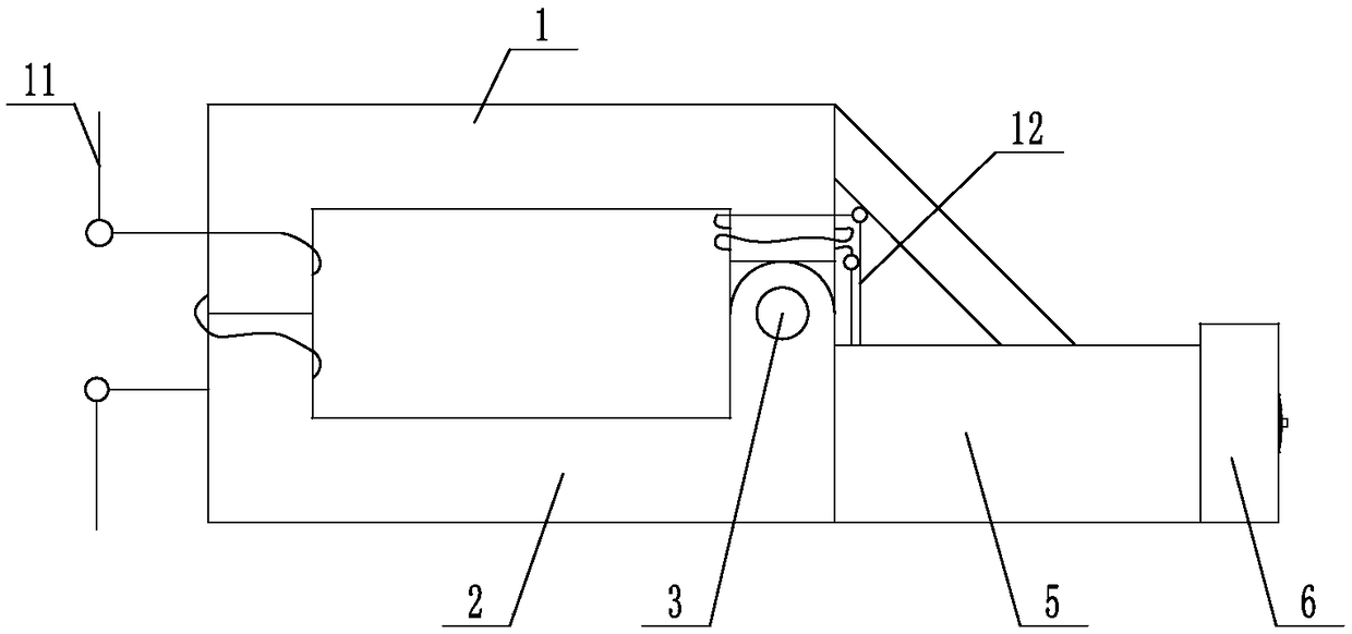
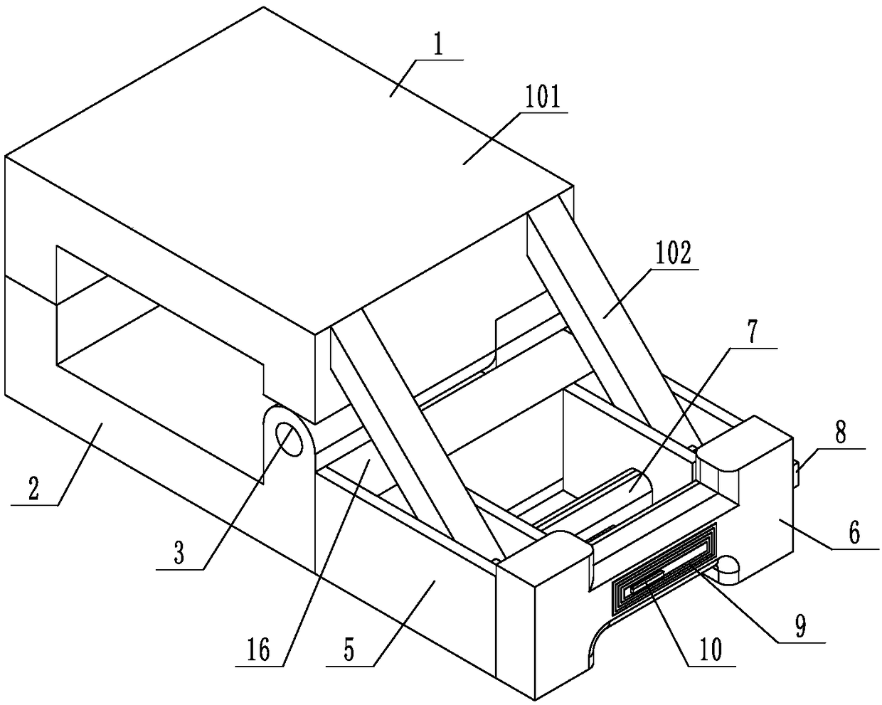
[0022] Such as Figure 1 to Figure 6 As shown, the wire loss detection device includes an upper claw 1 and a lower claw 2, the upper claw and the lower claw are hinged at the rotating shaft 3, and the two are hinged to form a mouth-shaped structure. One side of the upper claw is wound with a detection winding 12 , and the electric wire is wound in the entrance-shaped structure at the openings of the upper claw and the lower claw to form a current transformer for detecting the current passing through the electric wire 11 . The lower jaw is provided with a controller 16, and the controller 16 is connected with a detection winding. The controller 16 is provided with a measuring instrument and a protection circuit for detecting the electric wire current. The measuring instrument and the protection circuit are existing Technology, not too much introduction.

[0023] The wire loss detection device also includes a manual clamping assembly, and the manual clamping assembly includes a...


PUM


Abstract

The invention discloses a wire line loss detection device, and relates to the power supply equipment field. The wire line loss detection device comprises an upper jaw and a lower jaw, which are connected together in a hinged manner on a position of a rotating shaft. One side of the upper jaw is provided with a detection winding in a coiled manner, and a wire is disposed in a notch formed by the upper jaw and the lower jaw in a clamped manner. The lower jaw is provided with a controller, which is connected with a detection winding. A basic wire line loss detection problem is solved, and by comparing with an original record, whether the wire on the position is qualified is identified, and whether the wire is the thin copper wire is identified. The wire line loss detection device has advantages of compact design, portability, and abilities of facilitating carrying of workers in power industry for detection, identifying line loss condition quickly, and finding out electricity stealing phenomena timely.

Description

technical field [0001] The invention relates to the field of power supply equipment, in particular to a wire loss detection device. Background technique [0002] Line loss is the voltage or electric energy consumed by the resistance. The cross-sectional area and length of the wire determine the amount of resistance, and the current determines the amount of voltage or electric energy loss. The longer the power loss, the more power loss. In the process of power transmission, power transformation and distribution, the loss caused by the components of the power system, such as resistance, inductance, etc. Of course, in the actual governance, many aspects are involved. There are reasons for the grid structure, as well as reasons for metering equipment, station areas, electricity theft, and leakage. In real life, there are many potential safety hazards due to irregular operation. For example, replacing high-cost wires with low-cost wires will cause problems if the current is too ...

Claims


Application Information

Patent Timeline
Patent Type & Authority Patents(China)
IPC IPC(8): G01R31/08G01C1/00G01R27/02
CPCG01C1/00G01R27/02G01R31/08
Inventor 姬忠刚赵炜张俊峰
Owner JINAN CITY CHANGQING DISTRICT POWER SUPPLY CO OF STATE GRID SHANDONG ELECTRIC POWER CO
Learn More