
Water flow rate testing device of turbine blade of aviation engine

A technology of aero-engines and turbine blades, which is applied in the direction of measuring devices, testing of mechanical components, testing of machine/structural components, etc., can solve problems such as low measurement accuracy and errors, and achieve the effect of improving measurement accuracy

Inactive Publication Date: 2017-05-24
四川成发普睿玛机械工业制造有限责任公司
View PDF8 Cites 7 Cited by
  • Summary
  • Abstract
  • Description
  • Claims
  • Application Information

AI Technical Summary

Problems solved by technology

Since there is only one flowmeter, the existing two test devices can only measure the water flow of a certain type of turbine blade flow channel and air film hole. When using the same test device to measure the water flow of turbine blades with different flow When the flow rate is high, it will cause the problem of low measurement accuracy or even large error. This is because the characteristic of the flowmeter is that the measurement accuracy is high in the best measurement range in the middle of its range, and it is close to the minimum and maximum values ​​of the range. The measurement accuracy of the range at both ends is low or even the error is large

Method used


Image

  • Water flow rate testing device of turbine blade of aviation engine
  • Water flow rate testing device of turbine blade of aviation engine
  • Water flow rate testing device of turbine blade of aviation engine

Examples


Embodiment 1

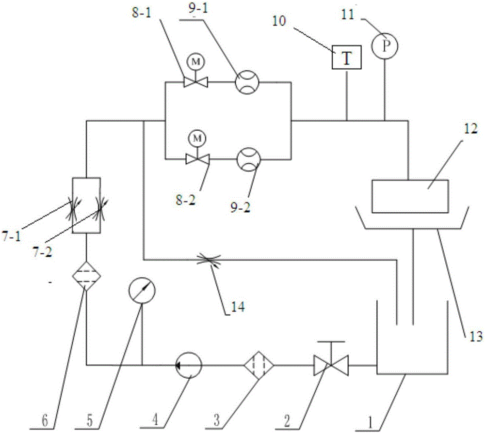
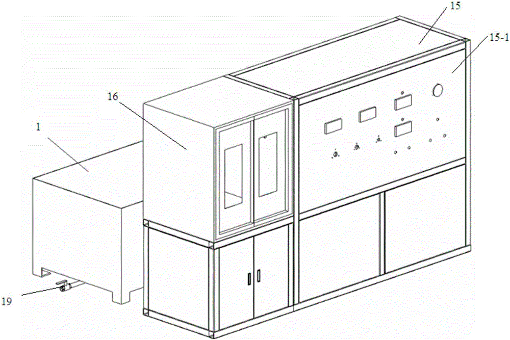
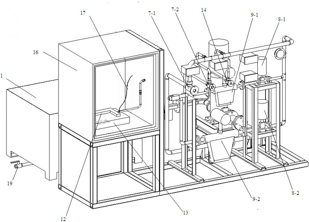
[0035] The aeroengine turbine blade water flow test device described in this embodiment has a structure such as Figure 1~5 As shown, it includes a water tank 1 provided with a drain port 19 and a top cover, a coarse filter 3, a centrifugal pump 4, a pressure gauge 5, a fine filter 6, a main road pressure regulating valve, a blade clamp 12, a workbench 13, and a The bypass flow path of the bypass regulating valve 14, two parallel measuring branches and the temperature sensor 10 and the pressure sensor 11; the two parallel measuring branches are the first measuring branch, the second measuring branch, the first measuring The first cut-off valve 8-1 and the first flowmeter 9-1 are installed in the branch from the water inlet to the water outlet in sequence, and the second cut-off valve 8-2 is installed in the second measurement branch from the water inlet to the water outlet in sequence. Two flow meters 9-2.

[0036] The water outlet of the water tank 1 is communicated with the...


PUM


Abstract

The invention relates to a water flow rate testing device of a turbine blade of an aviation engine. The water flow rate testing device comprises a water tank, a coarse filter, a water pump, a pressure gauge, a fine filter, a main path voltage regulation valve, a blade clamp, a worktable, a bypass flow passage, at least two parallel measuring branch lines, a temperature sensor and a pressure sensor, wherein the bypass flow passage is provided with a bypass adjusting valve; a cutoff valve and a flowmeter are arranged on each measuring branch line from the water inlet end to the water outlet end; the flowmeters on the measuring branch lines have different ranges. The water flow rate testing device of the turbine blade of the aviation engine has the advantages that the water flow rates of flow passages and air film holes of different turbine blades can be measured by one testing device, and the measuring accuracy is improved.

Description

technical field [0001] The invention belongs to the field of aero-engine non-standard parts, in particular to a water flow test device for engine turbine blades. Background technique [0002] According to the development requirements of the turbine blades of the engine, it is necessary to conduct a water flow test on the blades. By measuring the water flow of the air film holes and flow channels of the turbine blades, the conditions of the air film holes of the blades and the processing of the internal flow channels can be inspected to provide a reference for the selection of installed blades. This is convenient A water flow test device is required. There are mainly two types of existing aero-engine turbine blade water flow testing devices. The first structural principle diagram is as follows Figure 6 As shown, it consists of water tank 1, water tank switch 2, coarse filter 3, water pump 4, pressure gauge 5, buffer 20, fine filter 6, main road pressure regulating valve, fl...

Claims


Application Information

Patent Timeline
IPC IPC(8): G01M13/00
CPCG01M13/00
Inventor 彭冬张晨周海峰刘鹏覃俊彭友然
Owner 四川成发普睿玛机械工业制造有限责任公司
Learn More