
Drying device

A technology of drying equipment and drying cylinder, which is applied in the direction of drying solid materials, drying gas arrangement, lighting and heating equipment, etc. It can solve the problems of affecting industrial production steps and slow drying speed of dryers, so as to prevent long-term retention around materials , the effect of slowing down the drying speed

Inactive Publication Date: 2017-05-24
重庆禾坛机械有限公司
View PDF0 Cites 2 Cited by
  • Summary
  • Abstract
  • Description
  • Claims
  • Application Information

AI Technical Summary

Problems solved by technology

[0003] The purpose of the present invention is to overcome the shortcomings and deficiencies of the above-mentioned prior art, and provide a drying equipment, which is mainly aimed at non-powder materials, and solves the defects of slow drying speed of existing dryers and affecting industrial production steps

Method used


Image

  • Drying device
  • Drying device
  • Drying device

Examples


Embodiment

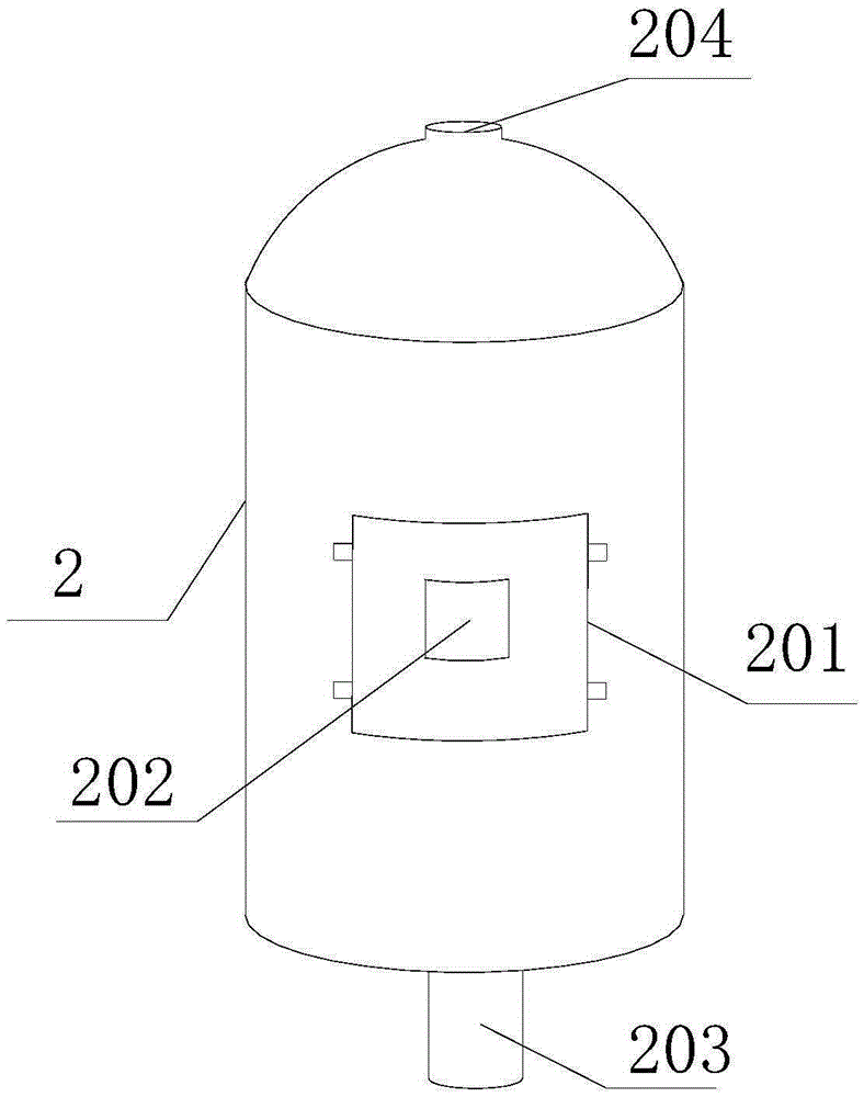
[0019] Such as Figure 1 to Figure 3 As shown, a drying device includes a frame 1 and a drying cylinder 2 fixed on the frame 1. The drying cylinder 2 is in the shape of a hollow cylinder, and a material door 201 is arranged on its side, and the inside is matched with the material door 201. The position is provided with a material rack, the frame 1 is provided with an air inlet device 3, the air inlet device 3 includes an air pump 301, a heater 302 and a dryer 303, and the air outlet of the air pump 301 is connected to the air outlet through the dryer 303 and the heater 302 The inlet 203 at the lower end of the drying cylinder 2 and the air inlet of the air pump 301 are connected to the outlet 204 at the top of the drying cylinder 2 .

[0020] It can be seen that in the present invention, wind heat is mainly used to heat the material, and the blower is to actively blow the hot air onto the material, and the heating speed is naturally faster. For example, in the prior art, a hea...


PUM


Abstract

The invention discloses a drying device. The drying device comprises a rack and a drying cylinder fixed to the rack. The drying cylinder is in a hollow cylinder shape. A material door is arranged on the side face of the drying cylinder, a material frame matched with the position of the material door is arranged in the drying cylinder, and an air inlet device is arranged on the rack. The air inlet device comprises an air pump, a heater and a dryer. An air outlet of the air pump communicates with an inlet in the lower end of the drying cylinder through the dryer and the heater. An air inlet of the air pump communicates with an outlet in the top of the drying cylinder. The top of the drying cylinder is in an inverted bowl shape. A spiral groove is formed in the side wall of the interior of the drying cylinder. The drying device has the beneficial effects that air heat is used for heating and drying materials, and compared with an ordinary electric heating device, the drying device can prevent the situation that vapor stays at the place around the materials for a long time and slows down drying; and the spiral groove is formed in the inner side of the drying cylinder of the drying device, air circulation is accelerated, vapor can be brought away more quickly, and the drying speed is increased.

Description

technical field [0001] The invention relates to the field of material drying, mainly the drying of non-powder materials, in particular to a drying device. Background technique [0002] Many fields of industry involve the drying of materials. It can be said that industrial production basically has a drying step, but the existing drying equipment basically puts the material in a box, and then heats and evaporates the moisture in the material. This method dries The speed is not fast enough, and the required time is too much, which greatly affects the progress of industrial production. The present invention is a series of transformations done to the drying equipment to solve this problem. Contents of the invention [0003] The object of the present invention is to overcome the shortcomings and deficiencies of the above-mentioned prior art, and provide a drying device, which is mainly aimed at non-powder materials, and solves the defects of the existing dryers that the drying s...

Claims


Application Information

Patent Timeline
IPC IPC(8): F26B21/00F26B25/00
Inventor 何敏
Owner 重庆禾坛机械有限公司
Learn More