Vacuum low-temperature grain drying machine

A vacuum low temperature, drying machine technology, applied in the direction of drying machine, drying, non-progressive drying machine, etc., can solve the problems of uneven drying moisture, long drying time, low heat conduction and heat dissipation efficiency, etc., to improve grain drying Efficiency, improved total heat transfer, optimized grain drying effect

Inactive Publication Date: 2017-05-24
张国利
View PDF0 Cites 0 Cited by
  • Summary
  • Abstract
  • Description
  • Claims
  • Application Information

AI Technical Summary

Problems solved by technology

[0002] The dryers currently on the market for grain drying use high-temperature and large-volume drying, and the hot air is carried out in the dryer. The entire drying process is atmospheric pressure and can dry the grain; Problems such as low heat utilization rate, high power consumption, poor drying effect, and long drying time
[0003] The grain vacuum drying equipment on the market now performs vacuum low-temperature drying on the grain in a low-pressure vacuum state, which solves the problem of high hot air temperature and poor quality of grain after drying; the heating of grain vacuum drying on the market is Metal pipes placed in parallel dissipate heat, with low heat conduction and heat dissipation efficiency, low exhaust efficiency, and poor control of vacuum, which causes the water vaporization temperature to rise, and the heat energy required for drying increases a lot, and the waste heat cannot be used; Grain has dead corners, and wet grain is easy to form agglomerates, which affects uneven drying moisture

Method used


Image

  • Vacuum low-temperature grain drying machine
  • Vacuum low-temperature grain drying machine

Examples


Embodiment

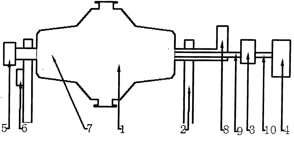
[0021] Such as figure 1 The shown vacuum low-temperature dryer for grain consists of a heat pipe type drying chamber (1), a bracket (2), a condenser (3), a vacuum pump (4), a heating device (5), a driving device (6), an air duct (10) Composition.

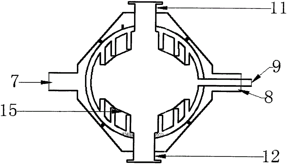
[0022] The thermal energy inlet (7) and thermal energy outlet (8) at both ends of the heat pipe type drying chamber (1) are installed on the support (2).

[0023] The driving device (6) is installed on the bracket (2), and the driving device (6) is used to drive the heat pipe type drying chamber (1) to rotate.

[0024] The thermal energy inlet (7) of the heat pipe type drying warehouse (1) is connected to the heating device (5) through the air duct (10); the heat energy outlet (8) of the heat pipe type drying warehouse (1) is connected through the air duct (10) to the heating unit (5).

[0025] The heating device (5) is a boiler.

[0026] The exhaust port (9) of the heat pipe type drying chamber (1) is connected to the condenser...


PUM


Abstract

The invention discloses a vacuum low-temperature grain drying machine. The vacuum low-temperature grain drying machine is composed of a heat-pipe drying bin, a support, a condenser, a vacuum pump, a heating device, a drive device and a gas guide pipe. The two ends of the heat-pipe drying bin are installed on the support, and the appearance shape of the heat-pipe drying bin is a cylinder. A heat energy inlet and a heat energy outlet of the heat-pipe drying bin are connected to the heating device through the gas guide pipe; and a gas exhaust port of the heat-pipe drying bin is connected to the condenser and the vacuum pump through the gas guide pipe, and a gas pressure in the heat-pipe drying bin achieves a vacuum degree of -0.094Mpa to -0.098Mpa. The inner wall of the drying bin is used for three-dimensional heat dissipation, and the heat dissipation area is increased by 5-30 times, so that a heat conduction and dissipation speed is increased, a grain drying time is shortened, continuous grain stirring can be realized, the grain drying efficiency is increased and the grain drying effect is optimized; and the effects of waste heat utilization, energy conservation and emission reduction are achieved.

Description

technical field [0001] The invention relates to a grain dryer, in particular to a grain vacuum low-temperature dryer. Background technique [0002] The dryers currently on the market for grain drying use high-temperature and large-volume drying, and the hot air is carried out in the dryer. The entire drying process is atmospheric pressure and can dry the grain; Problems such as low utilization rate of heat energy, high power consumption, poor drying effect, and long drying time. [0003] The grain vacuum drying equipment on the market now performs vacuum low-temperature drying on the grain in a low-pressure vacuum state, which solves the problem of high hot air temperature and poor quality of grain after drying; the heating of grain vacuum drying on the market is Metal pipes placed in parallel dissipate heat, with low heat conduction and heat dissipation efficiency, low exhaust efficiency, and poor control of vacuum, which causes the water vaporization temperature to rise, ...

Claims


Application Information

Patent Timeline
Patent Type & Authority Applications(China)
IPC IPC(8): F26B11/06F26B25/04A23B9/08
CPCY02A40/90Y02P60/85
Inventor 张国利
Owner 张国利
Why Eureka
Try Eureka