
Removable garden lamp

A garden lamp and lamp holder technology, which is applied in sustainable buildings, climate sustainability, outdoor lighting, etc., can solve the problems that solar lamps cannot be moved, and the utilization rate of solar panel power generation is low, so as to achieve rich functions and convenient daily life , good heat collection effect

Inactive Publication Date: 2017-05-24
HARBIN JINDU SOLAR ENERGY TECH
View PDF0 Cites 1 Cited by
  • Summary
  • Abstract
  • Description
  • Claims
  • Application Information

AI Technical Summary

Problems solved by technology

[0002] At present, with the advancement and promotion of solar energy technology, more and more lighting fixtures begin to use solar energy as the main energy supply, especially outdoor public lighting fixtures use a huge amount of solar energy, but in use, it is found that the current solar energy The positions of the solar panels equipped with the lighting fixtures are all fixedly installed on the lamp holders of the lighting fixtures, but because the position of the sun changes in a day, the solar panels can only be used when the sun is within a certain range. Performing power generation work, resulting in a relatively low utilization rate of solar panel power generation, and fixed solar lamps cannot be moved according to usage needs

Method used


Image

  • Removable garden lamp
  • Removable garden lamp

Examples


Embodiment 1

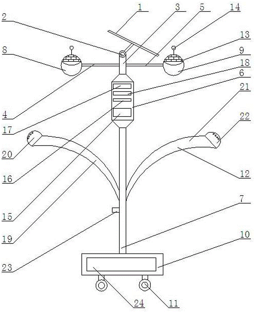
[0013] A movable garden light, comprising a solar heat collecting plate 1, an electric rotating shaft 2, an upper support column 3, a left cross bar 4, a right cross bar 5, a control box 6, a lower support column 7, a left lighting lamp 8, and a right lighting lamp 9. Lamp holder 10, universal wheel 11, spraying device 12, the solar collector plate 1 is connected to the upper end of the upper support column 3 through the electric rotating shaft 2, and the lower end of the upper support column 3 is installed on the control box 6 , the lower end of the control box 6 is connected to the lower support column 7, the lower support column 7 is installed on the lamp holder 10, the universal wheel 11 is installed at the bottom end of the lamp holder 10, and the left end of the upper support column 3 passes through The left crossbar 4 is connected to the left lighting lamp 8, and the right end of the upper support column 3 is connected to the right lighting lamp 9 through the right cro...

Embodiment 2

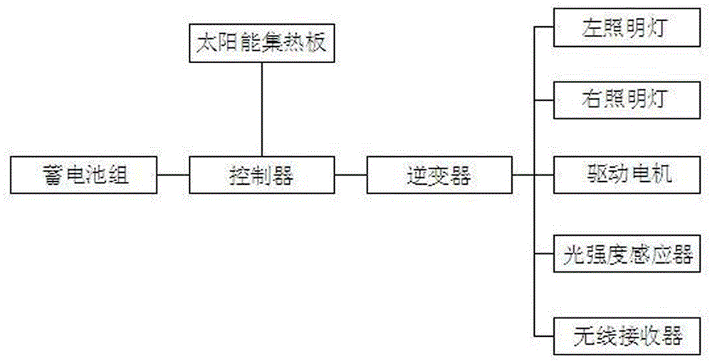
[0015] The solar thermal collector plate 1 is connected to the controller 15, the controller 15 is connected to the battery pack 24, and the controller 15 is connected to the left lighting lamp 8, the right lighting lamp 9, the drive motor 17, Light intensity sensor 14, wireless receiver 18.


PUM


Abstract

The invention relates to a removable garden lamp which comprises a solar heat collection plate, an electric rotating shaft, an upper supporting column, a left transverse rod, a right transverse rod, a control box, a lower supporting column, a left lighting lamp, a right lighting lamp, a lamp base, a universal wheel and a spraying device. The solar heat collection plate is connected to the upper end of the upper supporting column through the electric rotating shaft, the lower end of the upper supporting column is arranged on the control box, the lower end of the control box is connected with the lower supporting column, and the lower supporting column is arranged on the lamp base; the universal wheel is arranged at the bottom end of the lamp base, the left end of the upper supporting column is connected with the left lighting lamp through the left transverse rod, and the right end of the upper supporting column is connected with the right lighting lamp through the right transverse rod; and a controller, an inverter, a driving motor and a wireless receiver are arranged inside the control box, and the spray device is arranged on the lower supporting column. The removable garden lamp has the beneficial effect of being removable; and according to the removable garden lamp, a solar system is used for supplying power, wireless equipment can be used for controlling on and off of the lamp, the light intensity can be adjusted, and the direction of the solar heat collection plate can be automatically adjusted.

Description

technical field [0001] The invention relates to the field of manufacturing solar lamps and lanterns, in particular to a movable garden lamp. Background technique [0002] At present, with the advancement and promotion of solar energy technology, more and more lighting fixtures begin to use solar energy as the main energy supply, especially outdoor public lighting fixtures use a huge amount of solar energy, but in use, it is found that the current solar energy The positions of the solar panels equipped with the lighting fixtures are all fixedly installed on the lamp holders of the lighting fixtures, but because the position of the sun changes in a day, the solar panels can only be used when the sun is within a certain range. Performing power generation work, resulting in a relatively low utilization rate of solar panel power generation, and fixed solar lamps cannot be moved according to usage needs. Contents of the invention [0003] The purpose of the present inventi...

Claims


Application Information

Patent Timeline
IPC IPC(8): F21L4/08F21V23/04F21V33/00F21W131/109
CPCY02B20/72
Inventor 王永刚胡晶
Owner HARBIN JINDU SOLAR ENERGY TECH
Learn More