Reduction treatment method and reduction treatment furnace for metal ore

A processing method and technology for metal ore, applied in the field of metallurgy, can solve the problems of high reduction reaction temperature, complex equipment and high energy consumption, and achieve the effects of small equipment investment, small number of equipment and process cost saving.

Inactive Publication Date: 2017-05-24
江学艺
View PDF13 Cites 2 Cited by
  • Summary
  • Abstract
  • Description
  • Claims
  • Application Information

AI Technical Summary

Problems solved by technology

[0004] The technical problem to be solved by the present invention is to provide a metal ore reduction treatment method and a metal ore reduction treatment furnace. This method and the treatment furnace can solve the problems of complex equipment, large investment and reduction reaction temperature in the existing metal reduction method. High, high energy consumption problem

Method used


Image

  • Reduction treatment method and reduction treatment furnace for metal ore
  • Reduction treatment method and reduction treatment furnace for metal ore
  • Reduction treatment method and reduction treatment furnace for metal ore

Examples


Embodiment 1

[0021] Embodiment 1——the reduction treatment method of hematite:

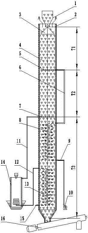
[0022] The equipment adopted in the present embodiment to the reduction of metal ore is as figure 1 As shown, there is a reduction treatment furnace for metal ores. There is a feed hopper 1 at the upper end of the reduction treatment furnace for metal ores. There is a flue gas outlet between the feed hopper 1 and the furnace shell 2 of the reduction treatment furnace for metal ores. The upper end inlet of the feed hopper 1 is the metal ore inlet of the metal ore to be reduced in the reduction treatment furnace of the metal ore. The lower end of the reduction treatment furnace of the metal ore is connected with a screw conveyor 16 through the collecting hopper part 8, and the metal ore of the screw conveyor 16 is The ore outlet is the metal ore outlet of the metal ore reduction treatment furnace, and the metal ore after the reduction reaction is exported out of the furnace from here.

[0023] The reduction trea...

Embodiment 10

[0036] Embodiment 10—the reduction treatment method of limonite:

[0037] The equipment adopted in the present embodiment to the reduction of metal ore is as Figure 5 As shown, there is a reduction treatment furnace for metal ores. There is a feed hopper 1 at the upper end of the reduction treatment furnace for metal ores. There is a flue gas outlet between the feed hopper 1 and the furnace shell 2 of the reduction treatment furnace for metal ores. The upper end inlet of the feed hopper 1 is the metal ore inlet of the metal ore to be reduced in the reduction treatment furnace of the metal ore. The lower end of the reduction treatment furnace of the metal ore is connected with a screw conveyor 16 through the collecting hopper part 8, and the metal ore of the screw conveyor 16 is The ore outlet is the metal ore outlet of the metal ore reduction treatment furnace, and the metal ore after the reduction reaction is exported out of the furnace from here.

[0038] The reduction tre...


PUM

PropertyMeasurementUnit
particle diameteraaaaaaaaaa

Abstract

The invention discloses a reduction treatment method and reduction treatment furnace for metal ore, belonging to the technical field metallurgy. The reduction treatment method for metal ore is implemented in the reduction treatment furnace with an upper metal ore inlet and a lower metal ore outlet. The reduction treatment furnace for metal ore is provided with a reducing gas outlet at a position located between the metal ore inlet and the metal ore outlet; a combustion-supporting gas outlet is arranged between the metal ore inlet and the reducing gas outlet; reducing gas is output from the reducing gas outlet and reacts with metal ore in a reducing zone; and combustion-supporting gas is input from the combustion-supporting gas outlet and supports combustion so as to realize preheating of metal ore in a preheating zone. The reduction treatment method and reduction treatment furnace for metal ore in the invention can be used for treating iron ore, manganese ore, copper core and the like with low metal content, and overcome the problems of complex equipment, great investment, high reduction reaction temperature and high energy consumption of conventional metal reduction methods.

Description

technical field [0001] The invention relates to the technical field of metallurgy, in particular to a method for reducing high-valence metals in metal ores to low-valence states. Background technique [0002] Most metals in nature exist in the form of compounds, but in order to obtain compounds with high metal content or simple metals, it is often necessary to carry out reduction and enrichment treatment. Different metals have different enrichment methods, but the principle is to reduce high-valence metals to low-valence states, such as Cu, MnO by reduction of CuO 2 Reduction gives Mn, from Fe 2 o 3 Reduction to get Fe and so on. [0003] The existing reduction treatment method of this metal ore, such as MnO 2 Reduction to Mn 2+ technology, which combines coal and MnO 2 The manganese ore is ground separately, then mixed in proportion, then added to the rotary kiln or shaft kiln and roasted at a temperature of 900°C ± 50°C. The reduction method of existing iron ore als...

Claims


Application Information

Patent Timeline
Patent Type & Authority Applications(China)
IPC IPC(8): C22B5/12
CPCC22B5/12
Inventor 江学艺
Owner 江学艺
Why Eureka
Try Eureka