Eureka AIR delivers breakthrough ideas for toughest innovation challenges, trusted by R&D personnel around the world.

Steel plate bin with coiled stacked discharging device

A steel silo and spiral technology, applied in the field of steel silos, can solve problems such as blockage, difficulty in material sliding, and large material sliding resistance

Inactive Publication Date: 2017-05-24
JIANGSU HENGXIN SILO EQUIP CO LTD
View PDF8 Cites 0 Cited by
  • Summary
  • Abstract
  • Description
  • Claims
  • Application Information

AI Technical Summary

Problems solved by technology

[0004] However, when the material slides downwards along the conveying plate, the material can only flow out from the open part at the bottom of the conveying plate and may encounter a situation where the sliding resistance of the material is relatively large, which will make it difficult for the material to slide down or even block the situation. occur

Method used


Image

  • Steel plate bin with coiled stacked discharging device

Examples


Embodiment Construction

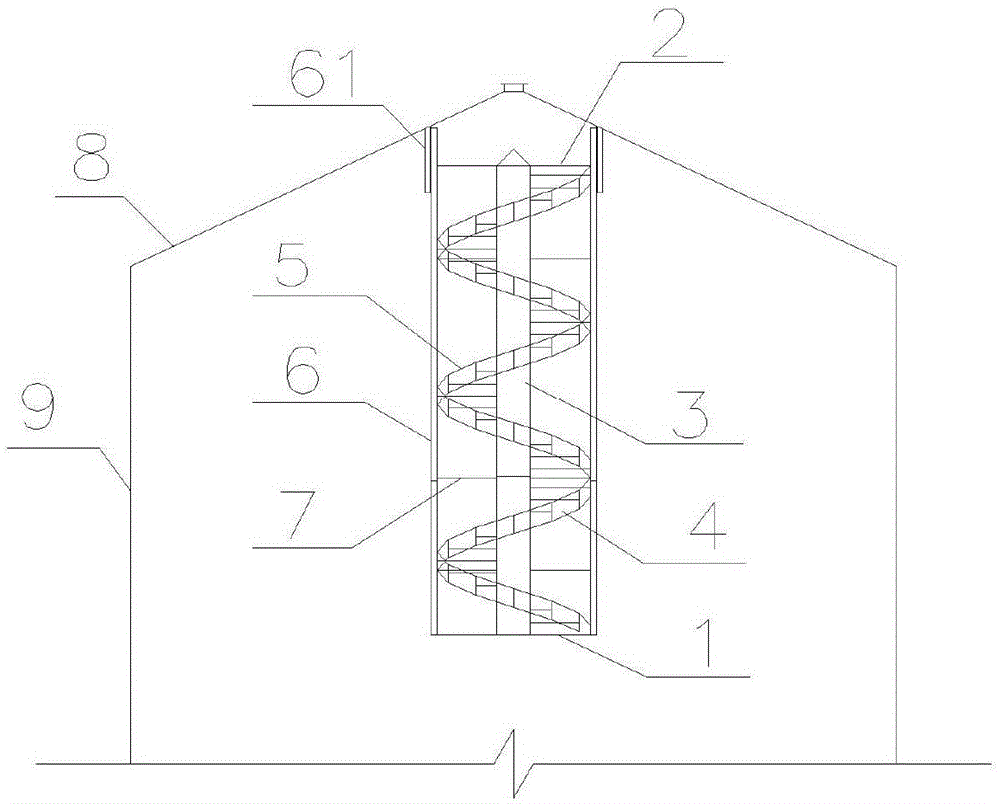
[0016] Such as figure 1 As shown, the spiral stacking and unloading device of the present invention includes a lower bracket 1 horizontally arranged on the bottom of the silo 9, and an upper bracket 2 connected to the top 8 of the silo, which is arranged at the center of the lower bracket 1 The supporting shaft 3 vertically extends to the center position of the upper bracket 2, and the stepped conveying plates 4 arranged at intervals are spirally arranged from top to bottom on the supporting shaft 3, and the conveying plates 4 are inclined downward along the spiral direction from top to bottom; in order to avoid When the material slides and falls along the conveying plate 4, it is thrown out and broken. The outer edge of the conveying plate 4 is provided with a baffle plate 5; 3 reinforced channel steel 6; a horizontal reinforcement bracket 7 parallel to the upper bracket 1 is welded between the lower bracket 1 and the upper bracket 2.

[0017] During use, the extended part 6...


PUM


Abstract

The invention discloses a steel plate bin with a coiled stacked discharging device. The steel plate bin comprises a lower support which is horizontally arranged on a silo bottom foundation of a silo, and an upper support connected with the silo top of the silo. A supporting shaft arranged in the center position of the lower support vertically extends to the center position of the upper support. Stepped conveying plates are spirally arranged on the supporting shaft at intervals from top to bottom. The conveying plates incline downwards from top to bottom in the spiral direction. A baffle is arranged at the outer edge of each conveying plate. The coiled stacked discharging device can effectively decrease the descending speed of materials, so that blocking of materials is avoided; and the structure is simple, no power is needed, low carbon and energy saving are achieved, and the effect is remarkable.

Description

technical field [0001] The invention relates to a steel silo with a spiral stacking and dropping device. Background technique [0002] The feeding principle of the traditional silo is that the material enters the silo from the feed port and falls freely to the bottom of the silo. During this process, the material acquires a great speed and has a great kinetic energy. When the material collides with the bottom of the warehouse, some fragile materials will be damaged, which will change the properties of the material, which is not suitable for some materials that have strict requirements on the properties. [0003] In this regard, Chinese patent application 201310657292.1 discloses a steel silo screw feeding device, which uses a shallow groove-shaped conveying plate for buffering and conveying. Specifically, it includes a lower bracket horizontally arranged on the bottom of the silo and a The upper bracket is horizontally arranged on the roof of the warehouse, the support shaf...

Claims


Application Information

Patent Timeline
Patent Type & Authority Applications(China)
IPC IPC(8): B65G65/32
Inventor 操文武彭旭东
Owner JIANGSU HENGXIN SILO EQUIP CO LTD
Why Eureka
Eureka Blog
Learn More