
High strength probe used for optical coherence tomography imaging

An optical coherence tomography, high-strength technology, applied in the direction of diagnosis, application, medical science, etc., can solve the problems of inconvenient clinical application, good mechanical properties, broken or damaged probes, etc., achieve good market prospects, improve mechanical strength, and service life long effect

Inactive Publication Date: 2017-05-24
哈尔滨医科大学附属第二医院 +1
View PDF5 Cites 6 Cited by
  • Summary
  • Abstract
  • Description
  • Claims
  • Application Information

AI Technical Summary

Problems solved by technology

This method has several disadvantages: there are subjective differences in visual observation, which may lead to inaccurate results; every time a catheter is replaced, the reference arm must be adjusted manually, which is time-consuming and laborious; professional training is required for operators before use It can be used correctly after a long time, which increases the operation complexity of the equipment and is quite inconvenient for clinical application.
[0004] In addition, the currently used probe processing methods mainly include the following two types: one is by gluing. Since the outer diameters of the single-mode fiber, the self-focusing lens and the turning lens may be different, the gluing method cannot guarantee a better quality. Mechanical properties, the probe may be broken or damaged when passing through the lesion; the mechanical properties of the probe are also related to the amount of glue dispensed, but the amount of glue dispensed should not be too much, otherwise it will affect the optical performance of the lens
Another kind of probe is made of single-mode fiber, self-focusing fiber and coreless fiber through fiber fusion and length cutting. This processing method is very fragile at the fusion point and has low mechanical strength.
Therefore, the current OCT probes generally have the problem of low mechanical strength, and they must be used with great care. If complex lesions are encountered, imaging can only be abandoned.

Method used


Image

  • High strength probe used for optical coherence tomography imaging

Examples


Embodiment Construction

[0019] The present invention will be further described below with reference to the accompanying drawings and examples, and the embodiments of the present invention include but not limited to the following examples.

[0020] Embodiment: In order to achieve the above object, the technical scheme adopted in the present invention is as follows:

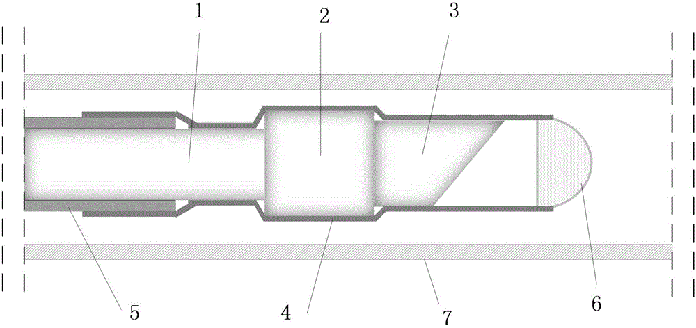
[0021] like figure 1 As shown, the present invention provides a high-intensity probe for optical coherence tomography, including a single-mode optical fiber 1, a self-focusing lens 2, a turning lens 3, a high-scattering rate heat-shrinkable tube 4, a torque cable 5, and a sealing cap 6 And the protective sleeve 7, the single-mode fiber 1, the self-focusing lens 2 and the turning lens 3 are connected together from left to right, the left end of the single-mode fiber 1 is in the hollow torque cable 5, and the high-scattering rate heat shrinkable tube 4 Cover the torque cable 5, single-mode optical fiber 1, self-focusing lens 2 and turning ...


PUM

PropertyMeasurementUnit
Lengthaaaaaaaaaa

Abstract

The invention discloses a high strength probe used for optical coherence tomography imaging. The high strength probe comprises a single-mode optical fiber, a grin-lens, a refraction lens, high scattering rate heat shrink tubes, a torque cable, a sealing cap and a protection sleeve. The single-mode optical fiber, the grin-lens and the refraction lens are connected together from left to right in sequence, the left end of the single-mode optical fiber is located in the hollow torque cable, the high scattering rate heat shrink tubes cover the torque cable, the single-mode optical fiber, the grin-lens and the refraction lens from left to right in sequence to form a probe structure, the protection sealing cap is installed at the right end of the probe structure, the probe structure is installed in the protection sleeve, and the torque cable transmits torque generated by an OCT system to the probe structure, so that the probe structure performs rotary motion and displacement translational motion in the protection sleeve.

Description

technical field [0001] The invention belongs to the field of medical equipment, in particular to a high-intensity probe for optical coherence tomography. Background technique [0002] Optical coherence tomography (OCT) technology is a new biomedical optical imaging method, which has high resolution (axial resolution 5-10 μm, lateral resolution 20-40 μm), fast imaging speed, The signal-to-noise ratio is high, so it quickly became a hot spot in the field of medical imaging. Endoscopic optical coherence tomography requires the orderly cooperation of equipment and catheters to perform corresponding imaging operations and obtain correct and clear images. In order to obtain the interference signal, it is necessary to ensure that the optical distances of the sample arm and the reference arm of the optical interference device are approximately equal. Since the catheter length of the sample arm will vary slightly, it is necessary to implement the optical path adjustment function in...

Claims


Application Information

Patent Timeline
IPC IPC(8): A61B1/05A61B1/00
CPCA61B1/05A61B1/00135A61B1/00163A61B1/00165A61B1/00172
Inventor 于波贾海波胡思宁田洁
Owner 哈尔滨医科大学附属第二医院
Learn More