Novel intelligent long service life high-end decelerator
A long-life, reducer technology, applied in mechanical equipment, transmission parts, belts/chains/gears, etc., can solve the problem of multiplication of reducer wear, reduce friction and wear, prolong service life, and avoid slippage.
- Summary
- Abstract
- Description
- Claims
- Application Information
AI Technical Summary
Problems solved by technology
Method used
Image

Examples
Embodiment 1
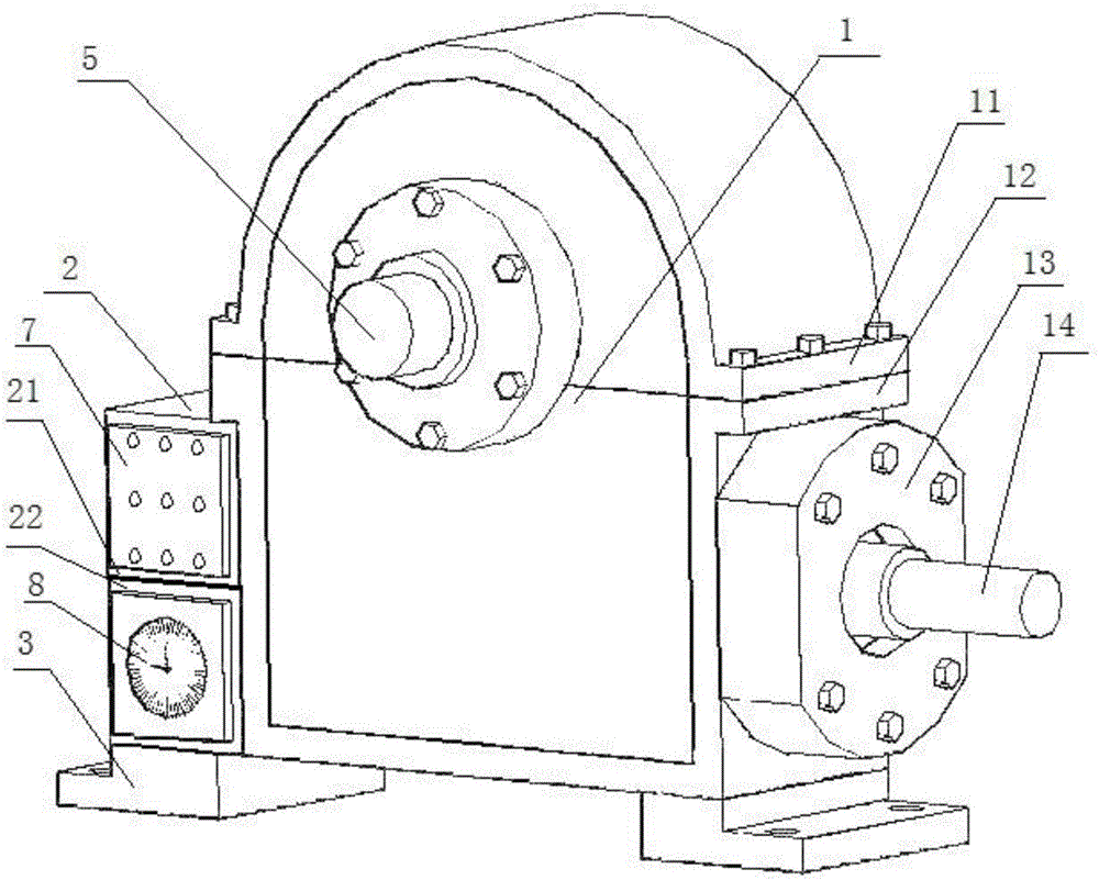
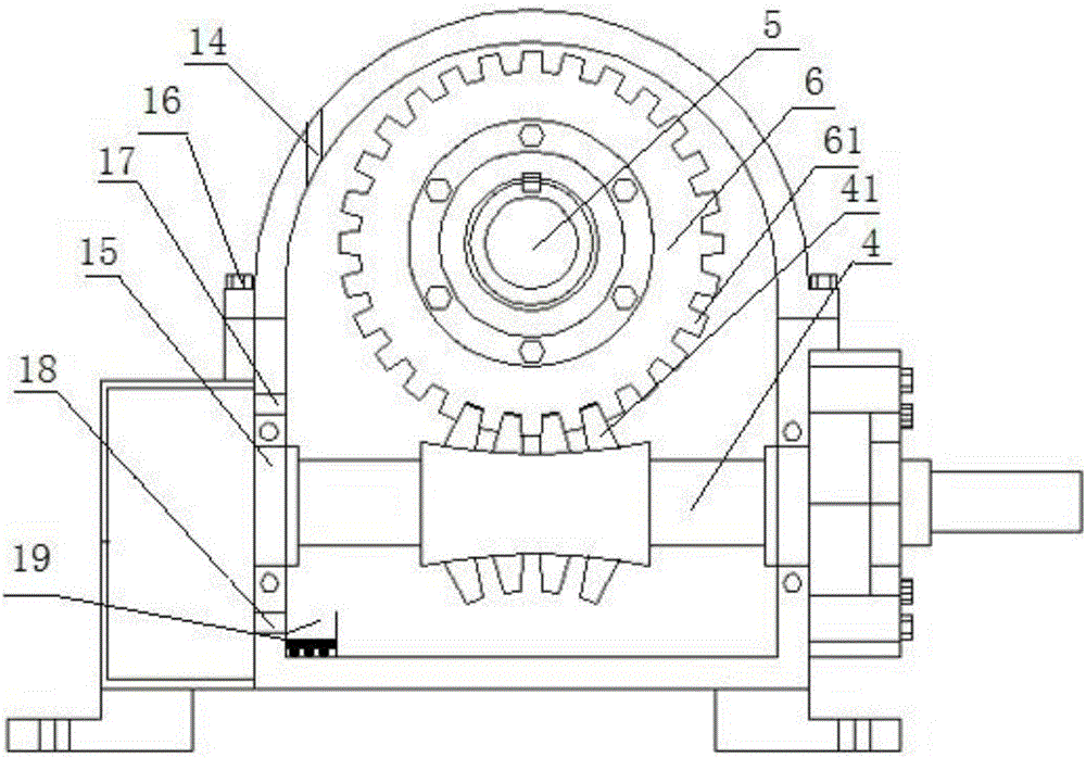
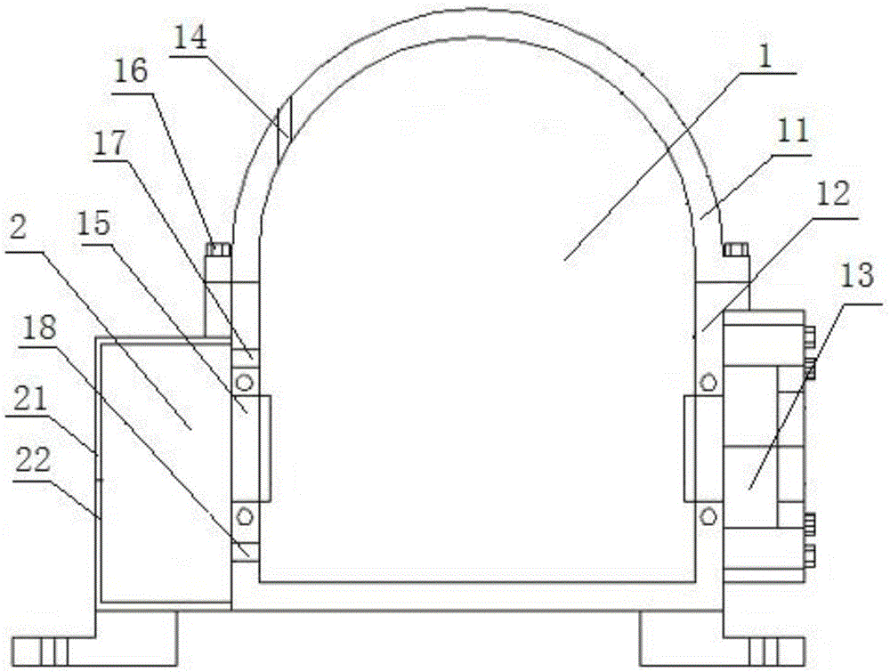
[0034] like Figure 1-Figure 2 As shown, a new intelligent long-life high-end reducer includes a fuel tank 1, a fixed orifice plate 3 co-cast with the fuel tank 1 is provided under the fuel tank 1, and a bearing 15 for installing a worm wheel 6 and a worm 4 is provided in the fuel tank 1 , the worm gear 6 and the worm screw 4 mesh with each other, and the oil tank 1 is filled with lubricating oil that has not passed the meshing position of the worm gear 6 and the worm screw 4. Extending to the outside of the oil tank 1, the connection between the output shaft 5, the worm 4 and the oil tank 1 is provided with a sealing cover 13 to prevent the leakage of lubricating oil, and the side of the oil tank 1 is provided with an auxiliary oil tank 2 for self-circulation cooling and storage of lubricating oil. The common wall between the oil tank 1 and the auxiliary oil tank 2 is provided with an upper oil hole 17 and a lower oil hole 18 for realizing self-circulation of lubricating oil ...
Embodiment 2
[0038] like figure 2As shown, further optimization is carried out on the basis of the new high-end reducer with lubricating oil cooling and heating self-circulation described in Example 1, so that it has the function of automatically absorbing lubricating oil residues, ensuring that the lubricating oil remains clear for a long time, and the lower oil hole 18 The bottom of the oil tank 1 below and the bottom of the fuel tank 1 on the opposite side of the lower oil hole 18 are provided with a dregs storage tank 19, and the size of the dregs storage tank 19 is 30*15*15 mm. The magnet is fixed with the dregs storage tank 19 through the insulating plate or insulating glue bonded at its bottom, and the notch of the dregs storage tank 19 is provided with a 35*10*1 mm stopper to prevent the dregs from being stored in the dregs storage tank 19. With the cold and hot self-circulation movement of the oil, it is drawn into the box again. The purpose of this embodiment is to make the iron...
Embodiment 3
[0041] Further optimization is carried out on the basis of the high-end reducer described in Embodiment 1 or 2. The wall thickness of the auxiliary oil tank 2 is 5 mm. Since the oil tank 1 is used to install the worm wheel 6 and the worm 4, it will carry the weight of the worm wheel 6 and the worm 4. And the impact force brought by high-speed rotation, in order to ensure sufficient strength, the thickness of fuel tank 1 must reach more than 20mm, and the auxiliary fuel tank 2 does not need to bear the weight of worm gear 6 and worm 4 and the impact force brought by high-speed rotation, so the auxiliary fuel tank 2 The strength requirements can be appropriately reduced, and the wall thickness of the auxiliary fuel tank 2 can be reduced to 1 / 5-1 / 4 of the tank wall thickness. This method can not only save manufacturing costs, but the key is that due to the thinner wall thickness, its heat dissipation performance will be greatly increased. .
PUM
 Abstract
Description
Claims
Application Information
 - R&D
- Intellectual Property
- Life Sciences
- Materials
- Tech Scout
- Unparalleled Data Quality
- Higher Quality Content
- 60% Fewer Hallucinations
Browse by: Latest US Patents, China's latest patents, Technical Efficacy Thesaurus, Application Domain, Technology Topic, Popular Technical Reports.
© 2025 PatSnap. All rights reserved.Legal|Privacy policy|Modern Slavery Act Transparency Statement|Sitemap|About US| Contact US: help@patsnap.com