A method and device for detecting the depth of casing leaks in oil production wells
A technology for oil production wells and casings, which is applied in the field of depth detection of casing leaks in oil production wells, and can solve the problems of high detection cost, slow detection efficiency, and inability to achieve rapid detection, etc.
- Summary
- Abstract
- Description
- Claims
- Application Information
AI Technical Summary
Problems solved by technology
Method used
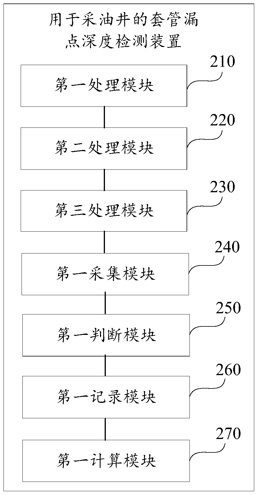
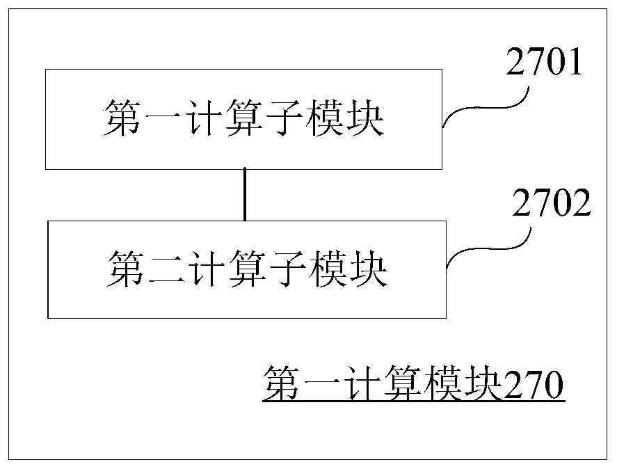
Image

Examples
Embodiment Construction
[0059] In order to make the objectives, technical solutions, and advantages of the present invention clearer, the embodiments of the present invention will be described in further detail below in conjunction with the accompanying drawings.
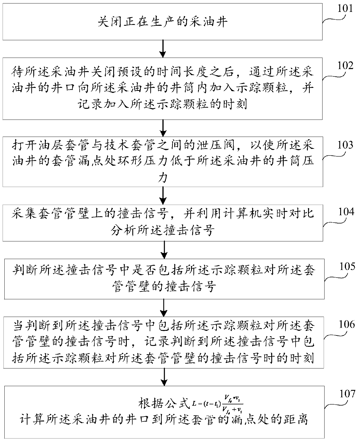
[0060] figure 1 It is a method for detecting the casing leak point depth of an oil production well provided by an embodiment of the present invention, see figure 1 , The method can include the following steps:
[0061] Step 101: Shut down the production well that is in production.
[0062] Specifically, the production well is closed by the Christmas tree at the wellhead of the production well, that is, the valve on the Christmas tree is closed to stop the production of oil in the production well, and the fluid in the production well is kept stable.
[0063] Step 102: After the oil production well is closed for a preset length of time, add tracer particles into the wellbore of the oil production well through the wellhead of the oil production well, ...
PUM
 Abstract
Description
Claims
Application Information
 - R&D
- Intellectual Property
- Life Sciences
- Materials
- Tech Scout
- Unparalleled Data Quality
- Higher Quality Content
- 60% Fewer Hallucinations
Browse by: Latest US Patents, China's latest patents, Technical Efficacy Thesaurus, Application Domain, Technology Topic, Popular Technical Reports.
© 2025 PatSnap. All rights reserved.Legal|Privacy policy|Modern Slavery Act Transparency Statement|Sitemap|About US| Contact US: help@patsnap.com