
Cooling control system of liquid cooling server and control method thereof

A control system and server technology, applied in cooling/ventilation/heating transformation, electrical components, electrical equipment structural parts, etc., can solve problems such as repeated debugging, and achieve the effect of increasing reliability

Active Publication Date: 2017-05-10
GUANGDONG SHENLING ENVIRONMENT SYST CO LTD
View PDF8 Cites 7 Cited by
  • Summary
  • Abstract
  • Description
  • Claims
  • Application Information

AI Technical Summary

Problems solved by technology

And at present, the liquid cooling temperature control unit uses the liquid outlet temperature of the internal circulation as the controlled parameter, which is used to control the frequency of the frequency conversion pump of the external circulation, the capacity adjustment of the cooling tower and the opening of the bypass valve, so that the internal circulation liquid The temperature T1 is kept constant within the range of the set point to ensure the heat dissipation requirements of the liquid-cooled server, and finally make the CPU temperature of the liquid-cooled server run in a reasonable temperature range (both safety and energy saving should be considered), but this method The disadvantage is that it needs repeated on-site debugging to determine a more reasonable temperature set point, and in actual use, certain corrections may be required due to the increase in load or changes in ambient temperature, so the existing control methods and solutions are still to be determined. Improve

Method used


Image

  • Cooling control system of liquid cooling server and control method thereof
  • Cooling control system of liquid cooling server and control method thereof

Examples


Embodiment Construction

[0020] In order to allow those skilled in the art to better understand the technical solution of the present invention, the present invention will be further described below in conjunction with schematic diagrams.

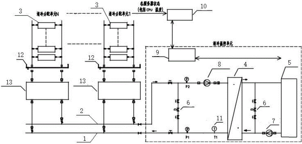
[0021] Such as figure 1 , a heat dissipation control system for liquid-cooled servers, including a liquid supply pipeline 1, a number of liquid-cooled servers 3, and a liquid return pipeline 2 connected in sequence, and a plate heat exchanger is connected between the liquid supply pipeline 1 and the liquid return pipeline 2 4, cooling tower 5 and bypass valve 6, the external circulation frequency conversion pump 7 is arranged on the liquid supply pipeline, and the external circulation frequency conversion pump 7 is located between the plate heat exchanger 4 and the cooling tower 5, and the liquid return pipeline 2 is provided with There is an internal circulation frequency conversion pump 8, and the internal circulation frequency conversion pump 8 is located betwee...


PUM


Abstract

The present invention discloses a cooling control system of a liquid cooling server and a control method thereof. The system comprises a liquid supply pipeline, a plurality of liquid cooling servers and a liquid return pipeline that are sequentially connected. A plate-type heat exchanger, a cooling tower and a bypass valve are connected between the liquid supply pipeline and the liquid return pipeline. The liquid supply pipeline is provided with an external circulation variable frequency pump. The liquid return pipeline is provided with an internal circulation variable frequency pump. The system further comprises a liquid cooling temperature control unit controller for acquiring CPU temperature of each liquid cooling server. The liquid cooling temperature control unit controller is connected with the external circulation variable frequency pump, the cooling tower and the bypass valve. The method comprises the step that the liquid cooling temperature control unit controller controls capacity input of the external circulation variable frequency pump and the cooling tower and opening degree of the bypass valve, so that the highest CPU temperature of all liquid cooling servers is stabilized within positive and negative deviation ranges of a set temperature. Through adoption of the cooling control system and the control method, when outflow liquid temperature is used as a controlled parameter, the work of determining a temperature setting point through debugging is omitted, and the whole system has high reliability.

Description

technical field [0001] The present invention relates to the field of server heat dissipation control, in particular to a liquid-cooled server heat dissipation control system and a control method thereof. Background technique [0002] At present, the principle of the server liquid cooling system is generally that the internal circulation pump drives the internal circulation coolant to the liquid cooling server to take away the heat of the server to the plate heat exchanger, and then drives the external circulation coolant through the external circulation pump to exchange the plate heat. The heat in the device is taken away to the cooling tower, and then the heat is dissipated to the air through the cooling tower. And at present, the liquid cooling temperature control unit uses the liquid outlet temperature of the internal circulation as the controlled parameter, which is used to control the frequency of the frequency conversion pump of the external circulation, the capacity a...

Claims


Application Information

Patent Timeline
IPC IPC(8): H05K7/20
CPCH05K7/20763H05K7/208H05K7/20836Y02D10/00
Inventor 原志锋陈健豪温军泉陈志宏韦成栋李敏华
Owner GUANGDONG SHENLING ENVIRONMENT SYST CO LTD
Learn More