
High-gain and low-profile vehicle-mounted antenna

A vehicle-mounted antenna, low-profile technology, applied to antennas, antennas suitable for movable objects, antenna arrays, etc., can solve the problems of radiation pattern deviation from the horizontal direction, signal dead zone, low gain in the horizontal direction, etc. Difficulty and cost reduction, energy consumption reduction, low cost effect

Active Publication Date: 2017-05-10
SOUTH CHINA UNIV OF TECH +1
View PDF9 Cites 3 Cited by
  • Summary
  • Abstract
  • Description
  • Claims
  • Application Information

AI Technical Summary

Problems solved by technology

[0003] In addition, the working environment of the external antenna on the vehicle is generally the roof, and the reflection effect of the metal roof will make the radiation pattern deviate from the horizontal direction, resulting in low gain in the horizontal direction
The existing vehicle-mounted external antennas are generally single-polarized omnidirectional radiation antennas, or single-polarized directional radiation antennas, and generally there are signal blind spots on the vertical plane

Method used


Image

  • High-gain and low-profile vehicle-mounted antenna
  • High-gain and low-profile vehicle-mounted antenna
  • High-gain and low-profile vehicle-mounted antenna

Examples


Embodiment

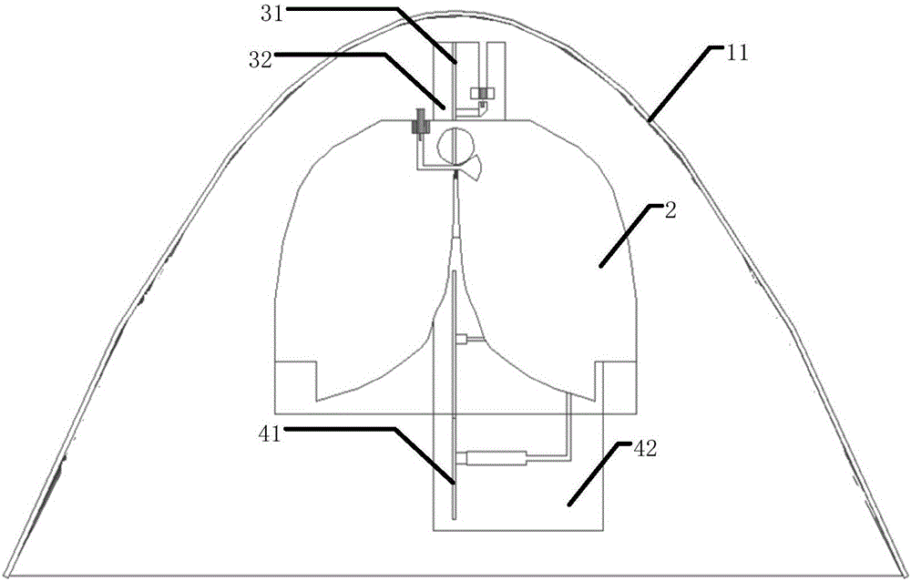
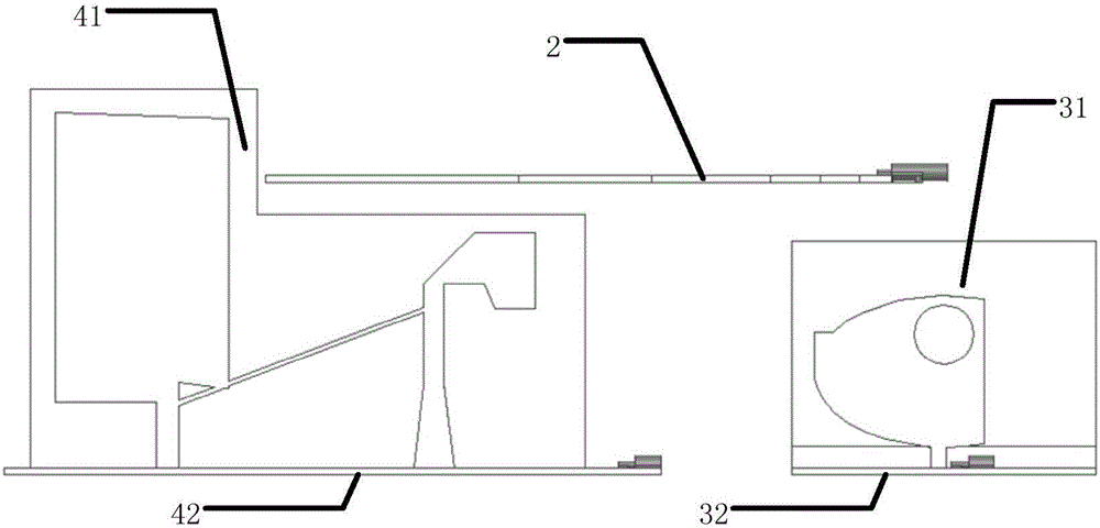
[0027] Such as figure 1 and figure 2 Shown, a kind of high-gain low-profile vehicle-mounted antenna includes a metal parabolic reflector 11 and a first antenna 31, a second antenna 2 and a third antenna 41 arranged in the metal parabolic reflector, the metal parabolic reflector 11 Installed on the roof of the car, the first antenna 31 and the third antenna 41 are respectively fixed on the metal parabolic reflector through the PCB structures 32 and 42 to realize power distribution and phase control.

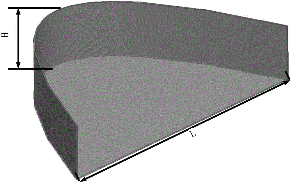
[0028] Such as image 3 As shown, the metal parabolic reflector 11 is in the form of a parabola, and the two parameters of the height H of the metal reflector and the width L of the aperture surface are adjusted to realize the antenna radiation performance, including the adjustment of the lobe width and the gain size. The height of the metal parabolic reflector is less than a quarter wavelength of the antenna's lowest operating frequency band, and has low-profile characteristic...


PUM


Abstract

The invention discloses a high-gain and low-profile vehicle-mounted antenna, which comprises a metal parabolic reflector, a first antenna, a second antenna and a third antenna, wherein the first antenna, the second antenna and the third antenna are arranged in the metal parabolic reflector; the metal parabolic reflector is arranged at the top of a vehicle; the first antenna is arranged at a focus position in the metal parabolic reflector; the second antenna comprises a horizontally polarized antenna; and the third antenna comprises two vertically polarized printed monopole antenna units, a power distributor and a neutral line structure connected with the two antenna units. Significant gain improvement is achieved by the first antenna and the second antenna through the metal parabolic reflector; control in a radiation direction and gain improvement in a horizontal direction are achieved by the third antenna through forming a small array; and the profile of the whole antenna is low.

Description

technical field [0001] The invention relates to the field of wireless mobile communication, in particular to a vehicle-mounted antenna with high gain and low profile. Background technique [0002] In recent years, with the rapid development of the telecommunications industry, the communication signaling interaction of various network communication standards of various operators has become increasingly intensive, which is highly dense in the time domain and seriously overlapped in the frequency domain. higher requirements. The antenna is an important part of the mobile communication device, which greatly affects the performance of the entire communication device. For example, the vehicle-mounted direction-finding system generally uses an external antenna. Due to the particularity of its equipment, the requirements for gain are relatively high, which are different from the general antennas used in mobile communication frequency bands. Common shark fin antennas or whip antenn...

Claims


Application Information

Patent Timeline
Patent Type & Authority Applications(China)
IPC IPC(8): H01Q15/16H01Q19/10H01Q1/32H01Q21/00H01Q21/24
CPCH01Q1/32H01Q15/16H01Q19/10H01Q21/00H01Q21/24
Inventor 章秀银李振辉曹云飞黄晓雄房俊彭国信
Owner SOUTH CHINA UNIV OF TECH
Learn More