Eureka AIR delivers breakthrough ideas for toughest innovation challenges, trusted by R&D personnel around the world.

Information transmission method and printing imaging device

An imaging device and information transmission technology, applied in the direction of digital output to the printing unit, etc., can solve the problems of low security, single working signal of printing imaging device, etc., and achieve the effect of improving security

Active Publication Date: 2019-09-17
APEX MICROELECTRONICS CO LTD
View PDF6 Cites 0 Cited by
  • Summary
  • Abstract
  • Description
  • Claims
  • Application Information

AI Technical Summary

Problems solved by technology

[0006] In the prior art, no matter what state it is in, the printing and imaging equipment uses a single working signal, and a third party can easily imitate the chip according to the signal of the printing and imaging equipment during use, which leads to the problem of low security

Method used


Image

  • Information transmission method and printing imaging device
  • Information transmission method and printing imaging device

Examples


Embodiment 1

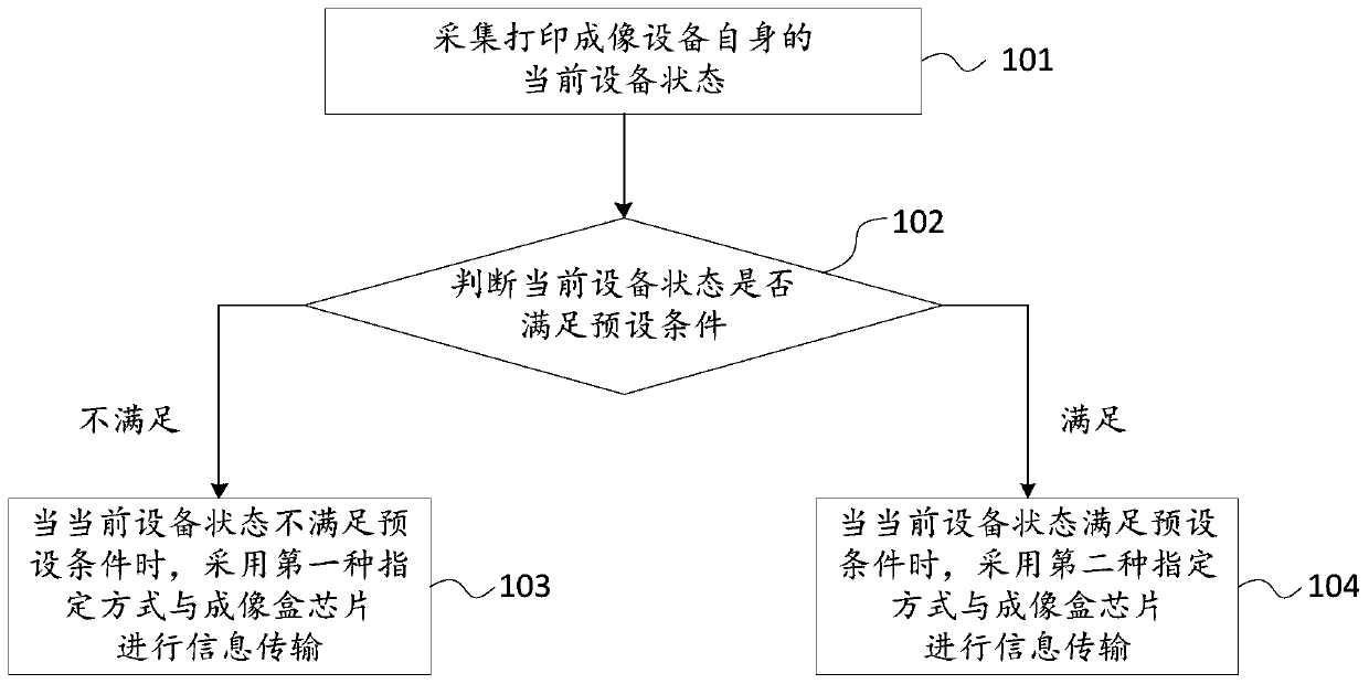
[0053] figure 1 The flow chart of the embodiment of the information transmission method provided by the embodiment of the present invention, such as figure 1 As shown, the information transmission method provided by the embodiment of the present invention may specifically include the following steps:

[0054] 101. Collect the current device status of the printing imaging device itself.

[0055] In the embodiment of the present invention, the information transmission method is mainly applied to a printing and imaging device. During use, the printing and imaging device can be divided into an initial state to be activated, a state in use, and a state to be upgraded with firmware. Among them, the initial status to be activated refers to the printing and imaging device needs to be activated before the printing and imaging device is used for printing for the first time, the in-use status refers to the printing and imaging device has been used for at least one printing, and the firm...

Embodiment 2

[0083] figure 2 A schematic structural diagram of an embodiment of a printing and imaging device provided for an embodiment of the present invention, as shown in figure 2 As shown, the printing and imaging device provided by the embodiment of the present invention may include: a collection unit 11 and a processing unit 12 .

[0084] Wherein, the collecting unit 11 is used to collect the current device state of itself;

[0085] The processing unit 12 is configured to use the first designated method to transmit information with the imaging cartridge chip when the current device status collected by the collection unit 11 does not meet the preset condition.

[0086] The processing unit 12 is also used to transmit information to and from the imaging cartridge chip in the second designated way when the current device status collected by the collection unit 11 satisfies the preset condition.

[0087] Wherein, the first designation method is different from the second designation m...


PUM


Abstract

The embodiment of the invention provides an information transmission method and a print imaging device. The information transmission method provided by the embodiment comprises the steps that a current device state of the print imaging device is acquired; when the current device state does not meet preset conditions, a first designated mode is adopted to perform information transmission with an imaging box chip; when the current device state meets the preset conditions, a second designated mode is adopted to perform information transmission with the imaging box chip, wherein the first designated mode and the second designated mode are different. In the technical scheme of the embodiment, the first designated mode and the second designated mode are the different designated modes and are simultaneously recorded in hardware of the print imaging device so that the print imaging device can read different designated modes in different device states for working, namely the print imaging device uses different signals in the different device states for working, the detection signal difficulty is high, and further the safety is improved.

Description

[0001] 【Technical field】 [0002] The invention relates to the technical field of printing and imaging, in particular to an information transmission method and a printing and imaging device. [0003] 【Background technique】 [0004] In an office environment, printing and imaging devices have become an indispensable product, and users use the printing and imaging devices to print documents on paper for preservation. In the prior art, printing and imaging devices can be classified into laser printing and imaging devices, inkjet printing and imaging devices, dot matrix printing and imaging devices, and the like. [0005] A printing and imaging device uses various signals during use, for example, a clock signal, an input / output signal, a voltage signal, a data signal, a power signal, and the like. Each type of printing and imaging device has a variety of fixed built-in signals, which are recorded in the hardware of the printing and imaging device. [0006] In the prior art, no mat...

Claims


Application Information

Patent Timeline
Patent Type & Authority Patents(China)
IPC IPC(8): G06F3/12
Inventor 李嘉荣张琳琳
Owner APEX MICROELECTRONICS CO LTD
Why Eureka
Eureka Blog
Learn More