
Body coil and magnetic resonance imaging system

一种磁共振成像、体线圈的技术,应用在测量磁变量、医药科学、诊断等方向,能够解决直流电源成本高、PIN二极管发热、增加直流损耗等问题,达到解决发热问题、降低射频损耗、减少组件的效果

Active Publication Date: 2017-05-10
SIEMENS SHENZHEN MAGNETIC RESONANCE
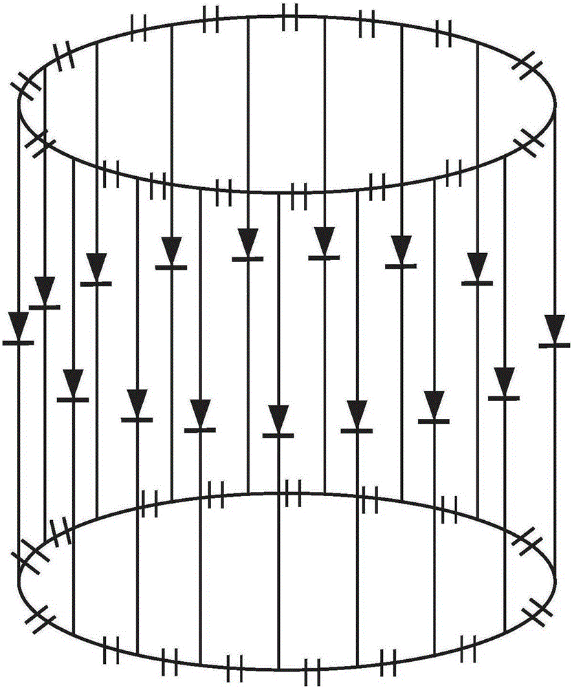
View PDF6 Cites 2 Cited by
  • Summary
  • Abstract
  • Description
  • Claims
  • Application Information

AI Technical Summary

Problems solved by technology

[0005] Although the currently commonly used body coil tuning / detuning scheme has no problem in function and is widely used, the DC power supply cost is very high because of the high supply current of the PIN diode; and when the body coil is in the tuning state, although sometimes Does not emit RF energy or only emits a small amount of RF energy, but still needs to continuously provide 4.8A DC, which increases unnecessary DC loss and causes heating problems of PIN diodes

Method used


Image

  • Body coil and magnetic resonance imaging system
  • Body coil and magnetic resonance imaging system
  • Body coil and magnetic resonance imaging system

Examples


Embodiment 1

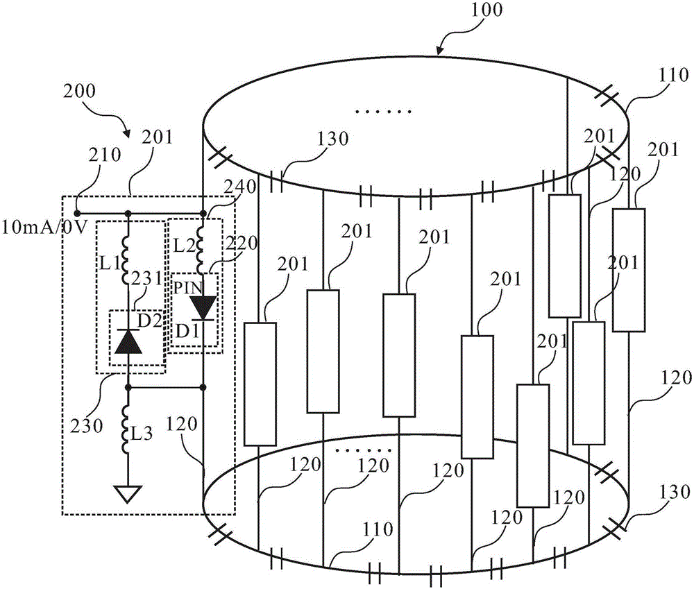
[0047] Figure 2A and Figure 2B It is a schematic structural diagram of the body coil in the first embodiment of the present invention. in, Figure 2B for Figure 2A A schematic diagram of the structure of the middle tuning and detuning circuit 200 sharing a general control signal interface.

[0048] like Figure 2A As shown, the body coil includes: a body coil body 100 and a tuning detuning circuit 200 .

[0049] The body coil body 100 includes two end rings 110, a plurality of uniformly distributed antenna legs 120 connected between the two end rings 110, and a plurality of antenna legs 120 disposed on the end rings and / or the antenna legs. A plurality of frequency tuning capacitors 130 . For different body coils, the number of antenna legs 120 may be different, for example, may be 16, 12, 8, or other numbers, which are not limited in this embodiment of the present invention. For the convenience of description, the embodiments herein sometimes take the case of includ...

Embodiment 2

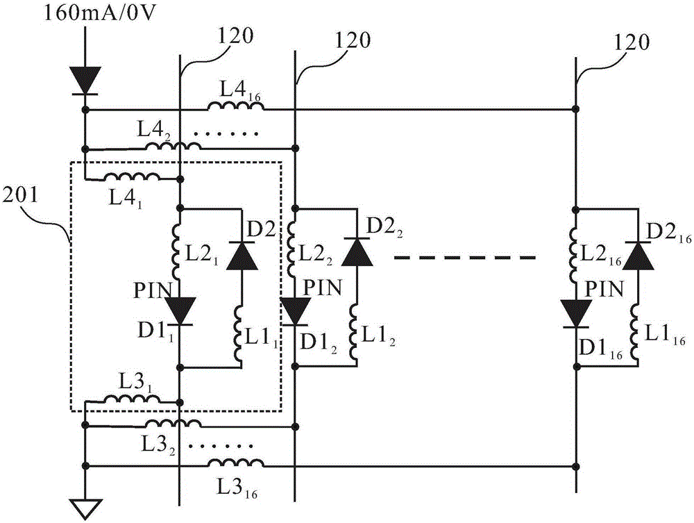
[0064] image 3 It is a schematic structural diagram of the body coil in the second embodiment of the present invention. like image 3 As shown, the body coil includes: a body coil body 100 and a tuning detuning circuit 300 .

[0065] The body coil body 100 includes two end rings 110, a plurality of uniformly distributed antenna legs 120 connected between the two end rings 110, and a plurality of antenna legs 120 disposed on the end rings and / or the antenna legs. A plurality of frequency tuning capacitors 130 . For different body coils, the number of antenna legs 120 may be different, for example, may be 16, 12, 8, or other numbers, which are not limited in this embodiment of the present invention. In addition, the body coil is not limited to a high-pass body coil, and may be a low-pass body coil or a band-pass body coil.

[0066] The tuning and detuning circuit 300 is connected to the body coil main body 100, and is used for performing tuning and detuning control on the b...

Embodiment 3

[0082] Figure 4 It is a schematic structural diagram of the body coil in the second embodiment of the present invention. like Figure 4 As shown, the body coil includes: a body coil body 100 and a tuning detuning circuit 400 .

[0083] The body coil body 100 includes two end rings 110, a plurality of uniformly distributed antenna legs 120 connected between the two end rings 110, and a plurality of antenna legs 120 disposed on the end rings and / or the antenna legs. A plurality of frequency tuning capacitors 130 . For different body coils, the number of antenna legs 120 may be different, for example, may be 16, 12, 8, or other numbers, which are not limited in this embodiment of the present invention. However, for the convenience of description, the third embodiment takes the case of 16 legs as an example for description. In addition, the body coil is not limited to a high-pass body coil, and may be a low-pass body coil or a band-pass body coil.

[0084] The tuning and detun...


PUM


Abstract

The invention discloses a body coil of a magnetic resonance imaging system, and a magnetic resonance imaging system. The body coil comprises a main body and a tuning and detuning circuit; the tuning and detuning circuit is connected with the main body for performing tuning and detuning control on the main body by use of control signals; the tuning and detuning circuit comprises a control signal interface, at least one switch diode unit and an AC-DC conversion circuit; the control signal interface is used for receiving control signals; the at least one switch diode unit is used for serial connection with at least one antenna leg and / or at least one end ring of the coil main body; and the AC-DC conversion circuit comprises a rectification circuit and is used for converting power of input radio frequency emission signals in the magnetic resonance imaging system into DC currents, the DC currents are used for providing DC currents for conduction of the switch diode unit. The body coil can reduce the cost of a DC power source and solves the problem of heating of a diode.

Description

technical field [0001] The invention relates to the technical field of magnetic resonance imaging systems, in particular to a body coil and a magnetic resonance imaging system for magnetic resonance imaging systems. Background technique [0002] Magnetic Resonance Imaging (MRI) is a technique for imaging using magnetic resonance phenomena. Magnetic resonance imaging (MRI) systems typically include a cavity-type superconducting magnet, gradient coils surrounding the superconducting magnet, a cavity-type body coil located within the gradient coil, an examination table board for placing the patient, and a section for covering the patient. Local coils at each site. Among them, the body coil can be used as both a transmitting coil and a receiving coil, and the local coil is mainly used as a receiving coil. Among them, the superconducting magnet provides a uniform main magnetic field B0 along the direction of the magnet axis, and the field strength of the main magnetic field B0 ...

Claims


Application Information

Patent Timeline
Patent Type & Authority Applications(China)
IPC IPC(8): G01R33/385A61B5/055
CPCG01R33/34076G01R33/3657G01R33/34046G01R33/3628
Inventor 佟瞳汪坚敏李文明马库斯·韦斯特
Owner SIEMENS SHENZHEN MAGNETIC RESONANCE
Learn More