Supersonic wave wind-speed and wind-direction measuring apparatus and measuring method

A wind speed and direction measurement device technology, applied in the measurement based on BP neural network algorithm compensation, ultrasonic wind speed and direction measurement device field, can solve the problem of affecting the accuracy of wind speed and wind direction measurement results, the fixed distance change of sending and receiving sensors, and the inability to accurately measure cold and warm airflow and other issues, to achieve the effect of easy promotion and use, high practical value and low cost

Pending Publication Date: 2017-05-10
NANJING UNIV OF INFORMATION SCI & TECH
View PDF5 Cites 11 Cited by
  • Summary
  • Abstract
  • Description
  • Claims
  • Application Information

AI Technical Summary

Problems solved by technology

When the wind speed and direction are actually measured by the ultrasonic time-of-flight method, shadow effects will be formed under different meteorological elements such as wind speed, wind direction, and structural parameters, which will greatly affect the accuracy of wind speed and wind direction measurement results.
The temperature sensor of the traditional anemometer is encapsulated in the device, which cannot accurately measure the external airflow of cold and warm; on the device, the lack of protection measures above the ultrasonic sensor will seriously affect the measurement accuracy. In addition, when the wind is strong, it will cause ultrasonic sensors. Vibration will cause the fixed distance between the transmitting and receiving sensors to change; moreover, the traditional 8 / 16-bit single-chip microcomputer is still widely used in the ultrasonic wind measuring instrument, which makes the measurement accuracy low
[0004] In summary, the ultrasonic wind measuring instrument or ultrasonic wind measuring device in the prior art still has the problem of inaccurate measurement results that needs to be solved urgently

Method used


Image

  • Supersonic wave wind-speed and wind-direction measuring apparatus and measuring method
  • Supersonic wave wind-speed and wind-direction measuring apparatus and measuring method
  • Supersonic wave wind-speed and wind-direction measuring apparatus and measuring method

Examples


Embodiment Construction

[0040] The present invention will be further described below in conjunction with the accompanying drawings. The following examples are only used to illustrate the technical solution of the present invention more clearly, but not to limit the protection scope of the present invention.

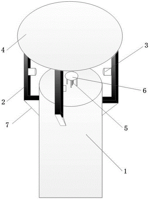
[0041] Such as figure 1As shown, an ultrasonic wind speed and direction measuring device of the present invention includes a mounting base 1, an ultrasonic sensor 3, a temperature sensor 5, and a wind speed and direction measurement unit arranged in the mounting base 1, and the mounting base 1 is directly above the mounting base. Circular protective cover 4, four pillars 2 are evenly arranged around the mounting base 1, and reinforcement ribs 7 are provided at the connection between the four pillars 2 and the mounting base 1, and the pillars 2 and the mounting base 1 are reinforced to prevent excessive wind speed. Large enough to cause the vibration of the pillar 2 to affect the measurement acc...


PUM


Abstract

The invention discloses a supersonic wave wind-speed and wind-direction measuring apparatus and measuring method. The apparatus comprises an installation base, supersonic wave sensors, a temperature sensor and a wind-speed and wind-direction measuring unit arranged in the installation base. The four supersonic wave sensors are divided into two groups which are disposed on the orthogonal axises of the same horizontal plane with two facing the other two in a horizontal manner. The temperature sensor is arranged on the upper surface of the installation base. The wind-speed and wind-direction measuring unit acquires the forward transmission time and the backward transmission time of the two groups of the supersonic wave sensors as well as the voltage signal inputted by the temperature sensor to obtain the actually measured data about the initial wind-speed, wind-direction and temperature. Then, a BP neural network model is established so as to obtain the corrected wind-speed and wind-direction expression. Based on the initial wind-speed, wind-direction and temperature, the corrected wind-speed and wind-direction are obtained. According to the invention, the BP neural network model is employed to correct the wind-speed and wind-direction, which eliminates the measurement errors caused by the shadow effect and obtains more accurate wind-speed and wind-direction values.

Description

technical field [0001] The invention belongs to the technical field of ultrasonic measurement, in particular to an ultrasonic wind speed and direction measurement device, and also to a measurement method based on BP neural network algorithm compensation. Background technique [0002] With the development of the times, wind speed and wind direction measurement is widely used in scientific experiments and industrial production, especially in the field of meteorology, high-precision wind speed and wind direction measurement plays a role that cannot be ignored. At present, wind speed and direction measurement methods are mainly divided into three categories, the first category: wing anemometer and cup anemometer, but this kind of measurement method is limited by the resistance of mechanical friction, and it is mostly used in the case of high wind speed; the second category : thermal anemometer, but the measurement method is limited to human intervention, which will seriously aff...

Claims


Application Information

Patent Timeline
IPC IPC(8): G01P5/24G01P13/02
CPCG01P5/245G01P13/02Y02A90/10
Inventor 李敏孙林峰张加宏匡晓华顾芳
Owner NANJING UNIV OF INFORMATION SCI & TECH
Why Eureka
Try Eureka