Underground cavity measuring method using flow quantity and flow velocity relationship
A technology of cavity and measuring device, applied in the field of surface subsidence survey, can solve the problems of complicated use of instruments, difficult maintenance, inconvenient measurement, etc., and achieve the effects of improving accuracy, overcoming narrow detection range and wide application range.
- Summary
- Abstract
- Description
- Claims
- Application Information
AI Technical Summary
Problems solved by technology
Method used
Image
Examples
Embodiment 1
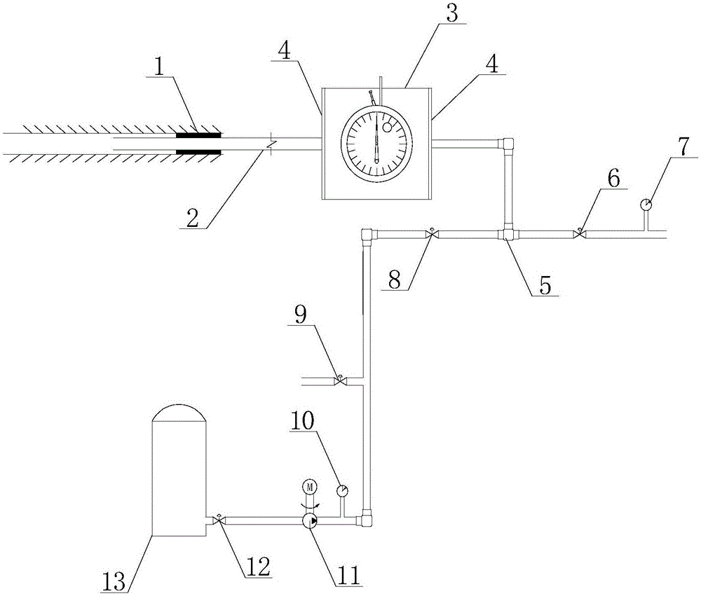
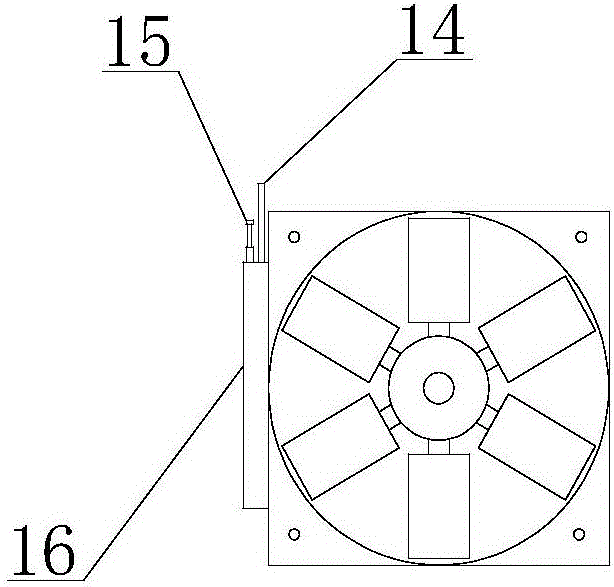
[0048] Embodiment 1: get a volume in the laboratory and be 12m 3 The gas storage tank is pumped into an approximate vacuum state, and an anemometer with a cross-sectional radius of 12cm is selected. First, the drill pipe is inserted into a section of pipeline connected to the gas storage tank, and the pipeline is blocked with a sealing capsule, and the second is closed. Stop valve 8, then open the first stop valve 6, observe the first pressure gauge 7, if the needle of the first pressure gauge rotates, it means that there is an underground cavity at the other end of the pipeline, immediately press the switch 14 of the biplane anemometer 3, and observe the counter 16. Record the wind speed every 3s, until the two-wing anemometer no longer rotates, press the switch 14 of the two-wing anemometer), and close the first cut-off valve 6, record the time used by the two-wing anemometer 3 from rotating to stop, As shown in Table 1.
[0049] Table 1
[0050]
[0051]
[0052] ...
PUM
 Abstract
Description
Claims
Application Information
 - R&D
- Intellectual Property
- Life Sciences
- Materials
- Tech Scout
- Unparalleled Data Quality
- Higher Quality Content
- 60% Fewer Hallucinations
Browse by: Latest US Patents, China's latest patents, Technical Efficacy Thesaurus, Application Domain, Technology Topic, Popular Technical Reports.
© 2025 PatSnap. All rights reserved.Legal|Privacy policy|Modern Slavery Act Transparency Statement|Sitemap|About US| Contact US: help@patsnap.com


