Valve device having anti-corrosion function
A valve device and anti-corrosion technology, which is applied to valve devices, diaphragm valves, engine components, etc., can solve problems such as corrosion, achieve flexible operation, and improve service life
- Summary
- Abstract
- Description
- Claims
- Application Information
AI Technical Summary
Problems solved by technology
Method used
Image
Examples
Embodiment 1
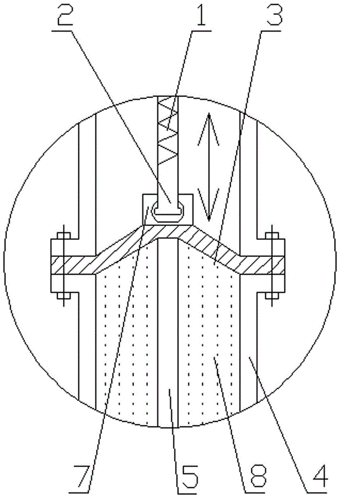
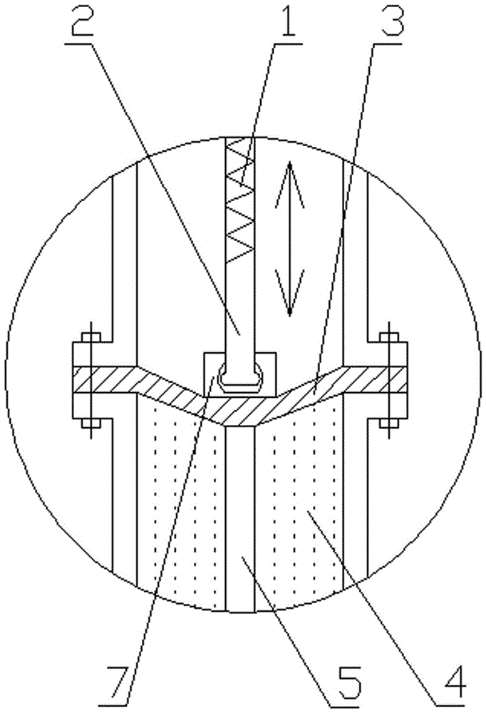
[0036] like figure 1 As shown, the separating device adopts a single-piece elastic spacer, the transition connector 7 is fixedly connected to the center of the upper end surface of the elastic spacer 3, and the top of the disc valve lifting rod 5 is vertically fixedly connected to the center of the lower end surface of the elastic spacer 3, The outer end of the elastic spacer 3 is fixedly connected with the valve seat 4 by bolts.
[0037] When the lifting and lowering lever is rotated, the center of the elastic spacer is lifted up, and the spacer is deformed. At the same time, the elastic spacer is lifted up to make the disc valve lifting rod separate from the water inlet of the valve seat, so that the medium can flow, such as figure 2 As shown; in the same way, press down the lifting rod to make the disc valve lifting rod block the water inlet of the valve seat and close the flow of the medium, such as image 3 shown. When the valve is working, the medium is always flowing...
Embodiment 2
[0039] like Figure 4 As shown, the partition device adopts a multi-piece elastic spacer structure, including several layers of steel sheets 9 that are superimposed in contact with each other from top to bottom and whose diameter increases layer by layer. The transition connector 7 is fixedly connected to the top steel sheet 9. In the center of the end face, an elastic gasket 10 is provided below the bottom steel sheet 9, and both the steel sheet 9 and the elastic gasket 10 are vertically installed on the disc valve lifting rod 5, and the outer end of the elastic gasket 10 is fixed to the valve seat 4 by bolts connect, Figure 4 The device indicates that the disc valve lifting rod blocks the water inlet of the valve seat.
[0040] When the lifting and lowering rod is rotated, the transition connecting piece drives the steel sheet to move up, thereby deforming the elastic gasket, separating the lifting rod of the disc valve from the water inlet of the valve seat, and allowing ...
Embodiment 3
[0042] like Image 6 As shown, the separation device adopts an expansion joint, the transition connector 7 is fixedly connected to the center of the upper end surface of the expansion joint 11, the top of the disc valve lifting rod 5 is vertically fixedly connected to the center of the lower end surface of the expansion joint 8, and the outer end of the expansion joint 8 is connected to the center of the lower end surface of the expansion joint 8. The valve seat 4 is fixedly connected by bolts.
[0043] When the lifting and lowering rod is rotated, the expansion and contraction is driven by the transition connector to deform and stretch upwards, so that the disc valve lifting rod is separated from the water inlet of the valve seat, so that the medium can circulate, such as Figure 7 shown. In the same way, when the lifting lever is rotated, the expansion and contraction will be deformed and stretched downward, so that the lifting lever of the disc valve will block the water i...
PUM
 Abstract
Description
Claims
Application Information
 - R&D Engineer
- R&D Manager
- IP Professional
- Industry Leading Data Capabilities
- Powerful AI technology
- Patent DNA Extraction
Browse by: Latest US Patents, China's latest patents, Technical Efficacy Thesaurus, Application Domain, Technology Topic, Popular Technical Reports.
© 2024 PatSnap. All rights reserved.Legal|Privacy policy|Modern Slavery Act Transparency Statement|Sitemap|About US| Contact US: help@patsnap.com


