Air suction structure of rotary cylinder piston compressor and rotary cylinder piston compressor

A technology for compressors and pistons, applied in the field of compressors, can solve problems such as the inability to reduce broadband noise, increase gas excitation force, increase compressor noise, etc., achieve good noise reduction effect, reduce suction pressure pulsation, reduce Effects of Broadband Noise

Active Publication Date: 2017-05-10
GREE ELECTRIC APPLIANCES INC +1
View PDF7 Cites 0 Cited by
  • Summary
  • Abstract
  • Description
  • Claims
  • Application Information

AI Technical Summary

Problems solved by technology

[0002] In the suction structure of the existing rotary cylinder piston compressor, such as Figure 1 to Figure 3 As shown, the refrigerant air flow enters the cylinder liner inner cavity 12 of the cylinder liner 1 directly from the liquid separator 2 through the refrigerant inlet pipe 11, because there are two exhaust gasses in each operation cycle of the rotary cylinder piston compressor, and the cylinder and the piston are also exhausted. There is a periodic rotational movement, resulting in a relatively large inspiratory pressure pulsation
Excessive suction pressure pulsation will increase the gas excitation force, thereby increasing the noise of the compressor; it will also increase the suction power consumption, resulting in a decrease in compressor performance
[0003] The frequency selectivity of the existing suction structure is strong, and it can only reduce the noise in a single frequency point or a narrow frequency band near this frequency point, but cannot reduce broadband noise, and the noise reduction effect is limited

Method used


Image

  • Air suction structure of rotary cylinder piston compressor and rotary cylinder piston compressor
  • Air suction structure of rotary cylinder piston compressor and rotary cylinder piston compressor
  • Air suction structure of rotary cylinder piston compressor and rotary cylinder piston compressor

Examples


Embodiment 1

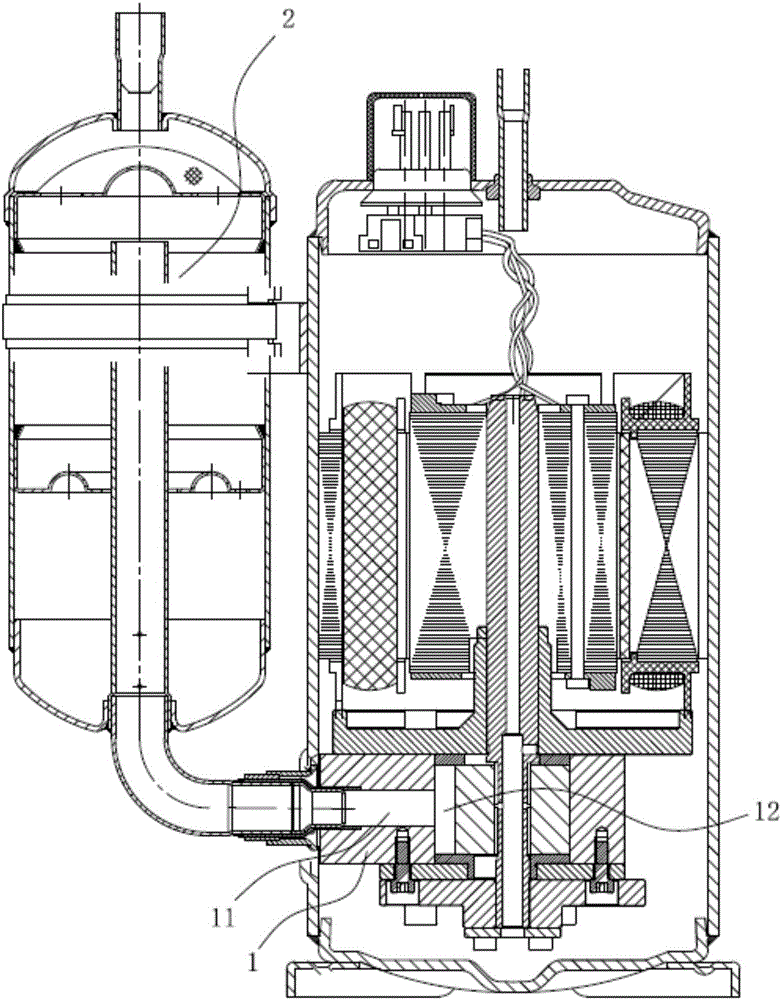
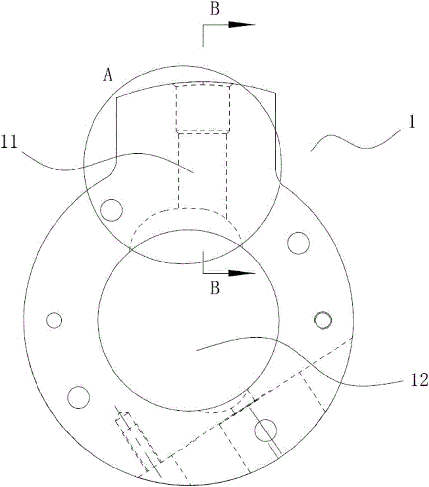
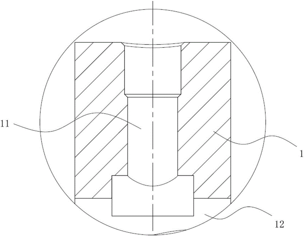
[0035] The preferred embodiment discloses an air suction structure of a rotary cylinder piston compressor. like Figure 4 to Figure 8 As shown, the air intake structure includes a cylinder liner 1 , and a refrigerant inlet pipe 11 is arranged on the side wall of the cylinder liner 1 , and the refrigerant inlet pipe 11 communicates with the inner cavity 12 of the cylinder liner and the liquid separator 2 . On the upper end surface, the lower end surface and / or the side wall of the cylinder liner 1, a muffler chamber main body 13 is arranged, and a neck passage 14 is connected between the side wall of the refrigerant inlet pipe 11 and the muffler chamber main body 13; in the muffler chamber main body 13 A sealing cover is provided on the outer surface.

[0036] By setting the muffler chamber on the cylinder liner 1 (including the muffler chamber main body 13 and the neck passage 14, which can also be called the Helmertz muffler chamber), the suction pressure pulsation is reduce...

Embodiment 2

[0041] This preferred embodiment discloses an air suction structure of a rotary cylinder piston compressor, which is basically the same as the first preferred embodiment. The difference is that if Figures 13 to 16 As shown, the anechoic cavity main body 13 includes a central subchamber 131 and at least one edge subchamber 132, and the central subchamber 131 and each edge subchamber 132 are connected by a subchamber pipeline 133; the neck channel 14 One open end of is located in the central subchamber 131.

[0042] That is, the main body 13 of the anechoic chamber is a combined type anechoic chamber (combined Helmhertz anechoic chamber) structure. Compared with the structure of single anechoic chamber (single Helmertz anechoic chamber) which can only reduce the pulsation peak value of a single frequency, each anechoic chamber (central sub-chamber 131, The edge sub-chambers 132) can be designed for different frequencies to be reduced, and cooperate with each other to realize ...

Embodiment 3

[0048] This preferred embodiment discloses a rotary cylinder piston compressor, including the suction structure of the rotary cylinder piston compressor described in the first or second preferred embodiment. like Figure 17 As shown, after the gaseous refrigerant enters the refrigerant pipe 11 from the liquid separator 2, a part of the gas enters the main body 13 of the muffler chamber through the neck channel 14, and the noise is eliminated by the principle of resonance sound absorption; the other part of the gas enters directly through the refrigerant pipe 11. The cylinder liner inner cavity 12 of the cylinder liner 1 . The impact of suction pressure pulsation on liquid distributor 2, suction pipe, cylinder liner 1, cylinder, piston and other parts is reduced, and the reliability of the whole machine is improved; the noise level of the whole machine is reduced, especially the suction Noise; the loss of suction power consumption is reduced, thereby improving the overall effi...


PUM


Abstract

The invention discloses an air suction structure of a rotary cylinder piston compressor and the rotary cylinder piston compressor, belongs to the technical field of compressors, and is designed to solve the problem that the existing structure has a limited muffler effect. The air suction structure of the rotary cylinder piston compressor disclosed by the invention comprises a cylinder liner, wherein a refrigerant inlet pipeline is arranged on the side wall of the cylinder liner; the refrigerant inlet pipe is communicated with the inner chamber of the cylinder liner and a dispenser; a muffler chamber main body is arranged on the upper end surface, the lower end surface and / or the side wall of the cylinder liner; a neck passage is connected between the side wall of the refrigerant inlet pipeline and the muffler chamber main body; a sealing cover is arranged on the outer side surface of the muffler chamber main body. According to the air suction structure of the rotary cylinder piston compressor and the rotary cylinder piston compressor disclosed by the invention, the air suction pressure pulsation is reduced, so that the air suction of the rotary cylinder piston compressor is steadier and smoother; the overall noise level is reduced; the loss of the air suction power consumption is reduced, and the overall efficiency of the rotary cylinder piston compressor is improved.

Description

technical field [0001] The invention relates to the technical field of compressors, in particular to a suction structure of a rotary cylinder piston compressor and a rotary cylinder piston compressor including the suction structure. Background technique [0002] In the suction structure of the existing rotary cylinder piston compressor, such as Figure 1 to Figure 3 As shown, the refrigerant air flow enters the cylinder liner inner cavity 12 of the cylinder liner 1 directly from the liquid separator 2 through the refrigerant inlet pipe 11, because there are two exhaust gasses in each operation cycle of the rotary cylinder piston compressor, and the cylinder and the piston are also exhausted. There is a periodic rotational motion, resulting in relatively large inspiratory pressure pulsations. Excessive suction pressure pulsation will increase the gas excitation force, thereby increasing the noise of the compressor; it will also increase the suction power consumption, resultin...

Claims


Application Information

Patent Timeline
Patent Type & Authority Applications(China)
IPC IPC(8): F04C29/06F04C29/12
Inventor 张金圈张荣婷杜忠诚胡余生徐嘉
Owner GREE ELECTRIC APPLIANCES INC
Why Eureka
Try Eureka