
Electric boost braking device

A brake device and electric power assist technology, which is applied in the direction of brake transmission device, foot-operated starting device, brake, etc., can solve the problems of reducing vehicle driving safety, low response speed, and difficult braking, etc., and meet the braking force requirements Low pressure, fast braking response, stable and reliable transmission

Active Publication Date: 2017-05-10
ZHEJIANG SANXING MECHANICAL & ELECTRONICSAL STOCK
View PDF14 Cites 11 Cited by
  • Summary
  • Abstract
  • Description
  • Claims
  • Application Information

AI Technical Summary

Problems solved by technology

However, due to the non-decoupling between the pedal simulator and the electric booster, the driver's pedaling force also needs to drive the motor of the electric booster to rotate at the same time. They are all high transmission output ratio settings, and it will be very difficult to drive the motor in reverse through the driver's pedal force. Therefore, when the electric booster fails, using the driver's pedal force to brake is not only The response speed is low, and the braking is difficult, which reduces the driving safety of the vehicle

Method used


Image

  • Electric boost braking device
  • Electric boost braking device
  • Electric boost braking device

Examples


Embodiment Construction

[0027] The present invention is specifically described below by the embodiment, only for further illustrating the present invention, can not be interpreted as the limitation of protection scope of the present invention, the technical engineer of this field can make some non-essential improvements and improvements to the present invention according to the content of the above-mentioned invention Adjustment.

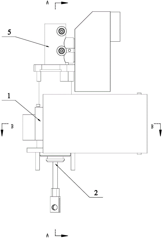
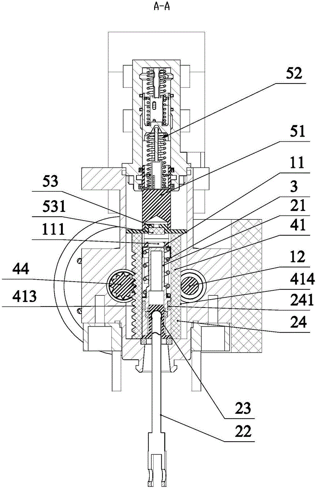
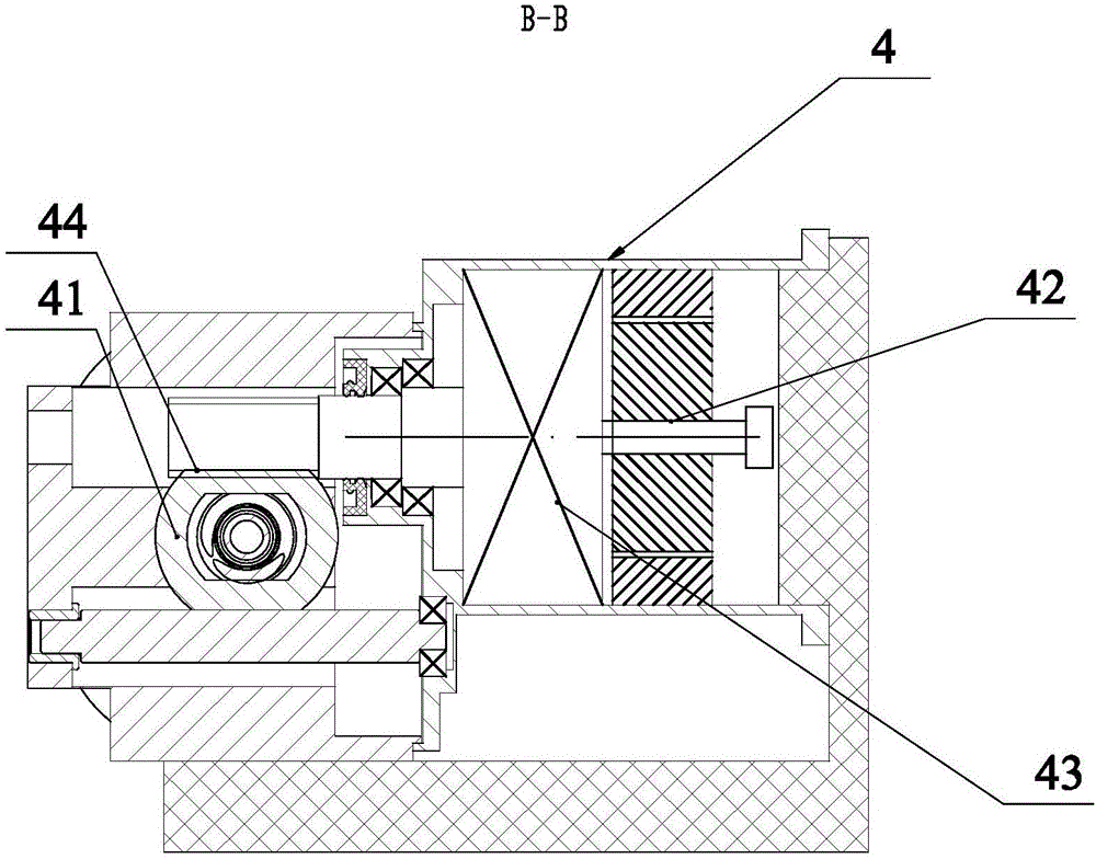
[0028] Such as Figure 1-8 The specific embodiment of the present invention shown includes a booster cylinder 1, a pedal assembly 2, a pedal return spring 3, an electric booster 4 and a brake pump assembly 5, and the brake pump assembly 5 There is a brake pump ejector rod 51 for receiving the braking force, and the electric booster 4 includes an electric powertrain, a booster sliding sleeve 41 that is slidably arranged in the booster cylinder 1 and provided with a sliding driving force by the electric powertrain. , the electric powertrain described in this embodiment incl...


PUM


Abstract

The invention discloses an electric boost braking device which comprises a boost cylinder body, a foot bar assembly, a foot bar reset spring, an electric booster and a brake pump assembly. A brake pump ejector rod used for receiving braking force is arranged on the brake pump assembly. The electric booster comprises an electric power assembly and a boost sliding sleeve, wherein the boost sliding sleeve is slidably arranged in the boost cylinder body, and sliding driving force of the boost sliding sleeve is provided by the electric power assembly. The boost sliding sleeve is in ejection fit with the brake pump ejector rod. The foot bar reset spring is arranged in an axial through hole and elastically connected with the head end of the foot bar assembly in a resettable mode. In the process that the head end of the foot bar assembly slides towards the brake pump ejector rod in the axial direction, the head end of the foot bar assembly sequentially penetrates through a positioning pin through hole and the outer end of the axial through hole in the boost sliding sleeve and acts on the brake pump ejector rod in an ejecting mode. The electric boost braking device has the advantages that the structure arrangement is reasonable, and the foot car braking force and the electric boost braking force are decoupled by each other.

Description

technical field [0001] The invention relates to a brake component for auto parts, in particular to an electric power-assisted braking device, which can be used in the fields of electric vehicles, hybrid vehicles, unmanned vehicles or intelligent driving vehicles. Background technique [0002] The braking system of traditional internal combustion engine vehicles mostly uses a vacuum booster device to assist the driver to generate sufficient braking force, and the vacuum source comes from the engine or a mechanical vacuum pump. For new energy vehicles (fuel cell vehicles and pure electric vehicles), there is no engine to provide a vacuum power source to provide braking boost, and the braking force generated by manpower alone cannot meet the needs of service braking. The electric power-assisted braking device can satisfy this demand very well. [0003] In recent years, major automobile and component manufacturers have launched similar electronic hydraulic braking systems one a...

Claims


Application Information

Patent Timeline
Patent Type & Authority Applications(China)
IPC IPC(8): B60T13/74B60T7/06
CPCB60T13/745B60T7/06
Inventor 周斯加蔡清理缪立春薛安志李峰平赵克刚
Owner ZHEJIANG SANXING MECHANICAL & ELECTRONICSAL STOCK
Learn More