
Automatic cutting and gluing machine

A gluing machine and cutting technology, applied in lamination auxiliary operations, chemical instruments and methods, lamination, etc., can solve the problem of large position errors in the electrical connection area of ​​conductive copper plates, increased production costs of sheet adhesive films, and gluing The position is prone to deviation and other problems, so as to overcome the easy deviation, improve work efficiency, and increase the speed of glue application

Active Publication Date: 2018-10-23
SHENZHEN ZHENQIN ELECTRONICS TECH
View PDF5 Cites 0 Cited by
  • Summary
  • Abstract
  • Description
  • Claims
  • Application Information

AI Technical Summary

Problems solved by technology

[0003] At present, the method of attaching a sheet-like adhesive film on the reserved electrical connection area on the conductive copper plate often requires first purchasing a cut sheet-like adhesive film of the required shape, and then manually pasting the adhesive. Paste the sheet-shaped adhesive film on the reserved electrical connection area on the conductive copper plate, and the purchase of a cut sheet-shaped adhesive film increases the production cost. Moreover, the speed of applying the adhesive is slow, the work efficiency is low, and it takes a lot of time. Labor force makes the production cost high; in addition, the way of manual gluing operation also has the disadvantage that the gluing position is prone to deviation, resulting in a large position error of the reserved electrical connection area on the conductive copper plate

Method used


Image

  • Automatic cutting and gluing machine
  • Automatic cutting and gluing machine
  • Automatic cutting and gluing machine

Examples


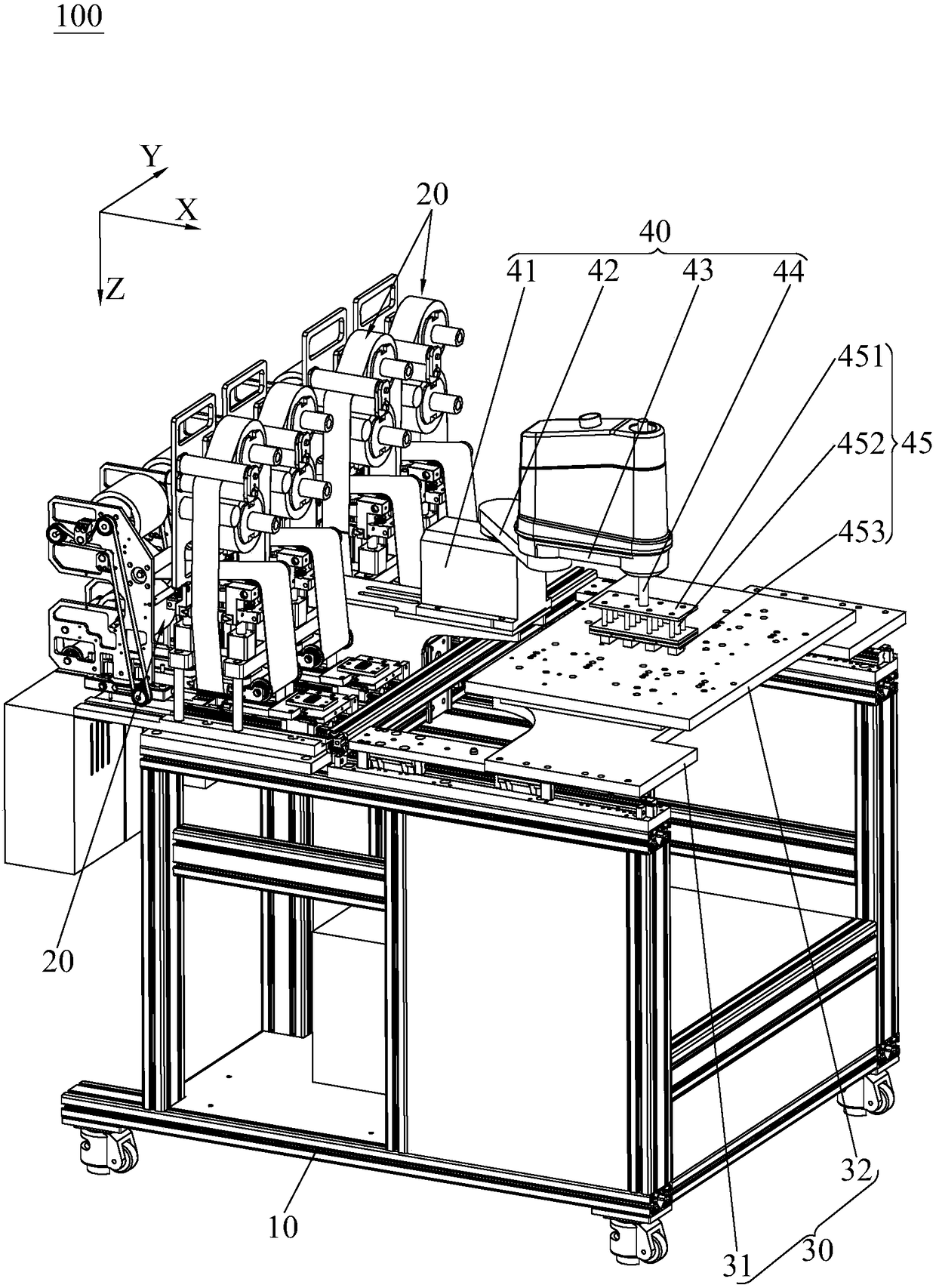
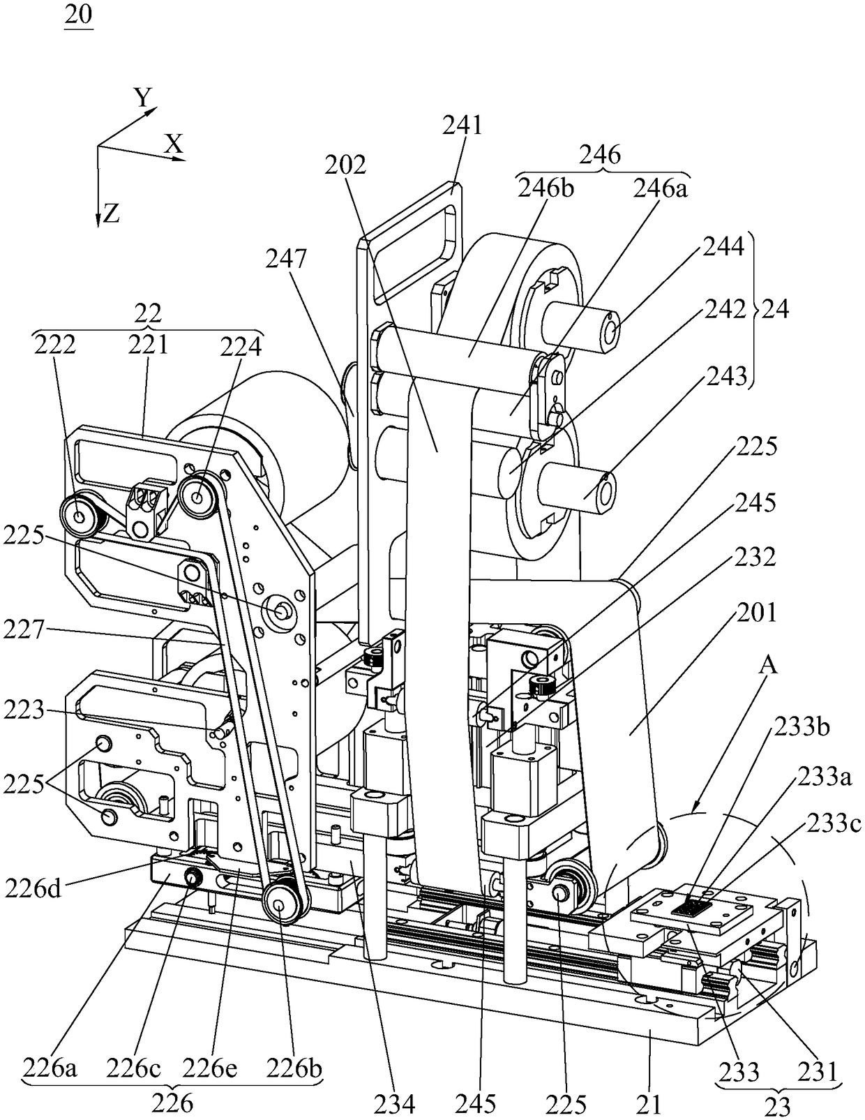
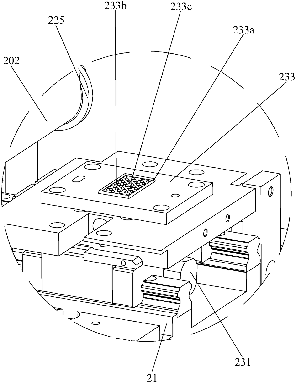
Embodiment Construction

[0027] Embodiments of the present invention will now be described with reference to the drawings, in which like reference numerals represent like elements.

[0028] see figure 1 and figure 2 , the automatic cutting and gluing machine 100 of the present invention comprises a frame 10, a carrying platform 30, a gluing manipulator 40 and four slicing devices 20, and the slicing device 20 includes a fixed substrate 21, a film conveying mechanism 22 and a film slicing mechanism 23 , the fixed substrate 21 is arranged on the frame 10, the adhesive film conveying mechanism 22 and the adhesive film slicing mechanism 23 are all arranged on the fixed substrate 21, and the adhesive film conveying mechanism 22 sends the strip-shaped adhesive film 201 to be cut into the adhesive film slice Mechanism 23, the adhesive film slicing mechanism 23 cuts out the sheet adhesive film (not shown in the figure) from the strip adhesive film 201, and the adhesive film conveying mechanism 22 rolls up t...


PUM


Abstract

The invention discloses an automatic cutting and rubberizing machine, which comprises a rack, a bearing platform, a rubberizing manipulator, and at least one cutter, wherein the cutter comprises a fixed base plate, an adhesive film-conveying mechanism, and an adhesive film-cutting mechanism, the fixed base plate is arranged on the rack, the adhesive film-conveying mechanism and the adhesive film-cutting mechanism are both arranged on the fixed base plate, the adhesive film-conveying mechanism conveys a to-be-cut strip-shaped adhesive film into the adhesive film-cutting mechanism, the adhesive film-cutting mechanism cuts out sheet adhesive films from the strip-shaped adhesive film, and the adhesive film-conveying mechanism rolls the strip-shaped adhesive film cut by the adhesive film-cutting mechanism; the bearing platform is arranged on the rack, to-be-rubberized products are borne by the bearing platform, and the bearing platform can drive the borne products to move; and the rubberizing manipulator attaches the sheet adhesive films at preset positions on the products. The automatic cutting and rubberizing machine disclosed by the invention can implement automatic cutting and rubberizing, and has the advantages of high rubberizing speed, manual operation replacement, production cost reduction and accurate rubberizing position.

Description

technical field [0001] The invention relates to the technical field of product film sticking equipment, in particular to an automatic cutting and sticking machine. Background technique [0002] As we all know, in the power communication industry, products such as conductive copper plates are often used. The conductive copper plate needs to be sprayed with an insulating layer, while the electrical connection area on the conductive copper plate that is reserved for electrical connection with the outside does not need to be sprayed with an insulating layer. Therefore, in The electrical connection area reserved on the conductive copper plate needs to be pasted with a sheet of adhesive film in advance to prevent the insulating layer from being directly sprayed on the electrical connection area. It can be realized that the reserved electrical connection area on the conductive copper plate will not be sprayed with an insulating layer. [0003] At present, the method of attaching a...

Claims


Application Information

Patent Timeline
Patent Type & Authority Patents(China)
IPC IPC(8): B32B37/00B32B38/00
CPCB32B37/00B32B38/0004
Inventor 王健
Owner SHENZHEN ZHENQIN ELECTRONICS TECH
Learn More