
Screw machining waste compaction device used in small-scale industry

A compacting device, an industrial technology, applied in the direction of stamping machines, presses, manufacturing tools, etc., can solve the problems of steel wire waste occupying a large space, compacting equipment with large volume, and expensive price, etc., and achieve simple structure and reasonable design , Improve the effect of manpower

Inactive Publication Date: 2017-05-10
李国朋
View PDF9 Cites 3 Cited by
  • Summary
  • Abstract
  • Description
  • Claims
  • Application Information

AI Technical Summary

Problems solved by technology

[0002] The screw thread forming work is often processed by small manufacturers or sellers, and after the thread cutting work is completed, a large amount of steel wire waste will inevitably be generated, and the steel wire waste will take up a lot of space, and, although large production plants There are corresponding large-scale recycling equipment, but small manufacturers and sellers need corresponding compaction equipment to compact the screw processing waste, so as to reduce the volume of the waste, so as to facilitate the storage and transfer of waste, and the traditional Compaction equipment often depends on power supply, resulting in large compaction equipment and relatively expensive prices

Method used


Image

  • Screw machining waste compaction device used in small-scale industry
  • Screw machining waste compaction device used in small-scale industry
  • Screw machining waste compaction device used in small-scale industry

Examples


Embodiment Construction

[0015] The present invention will be further described below in conjunction with accompanying drawing:

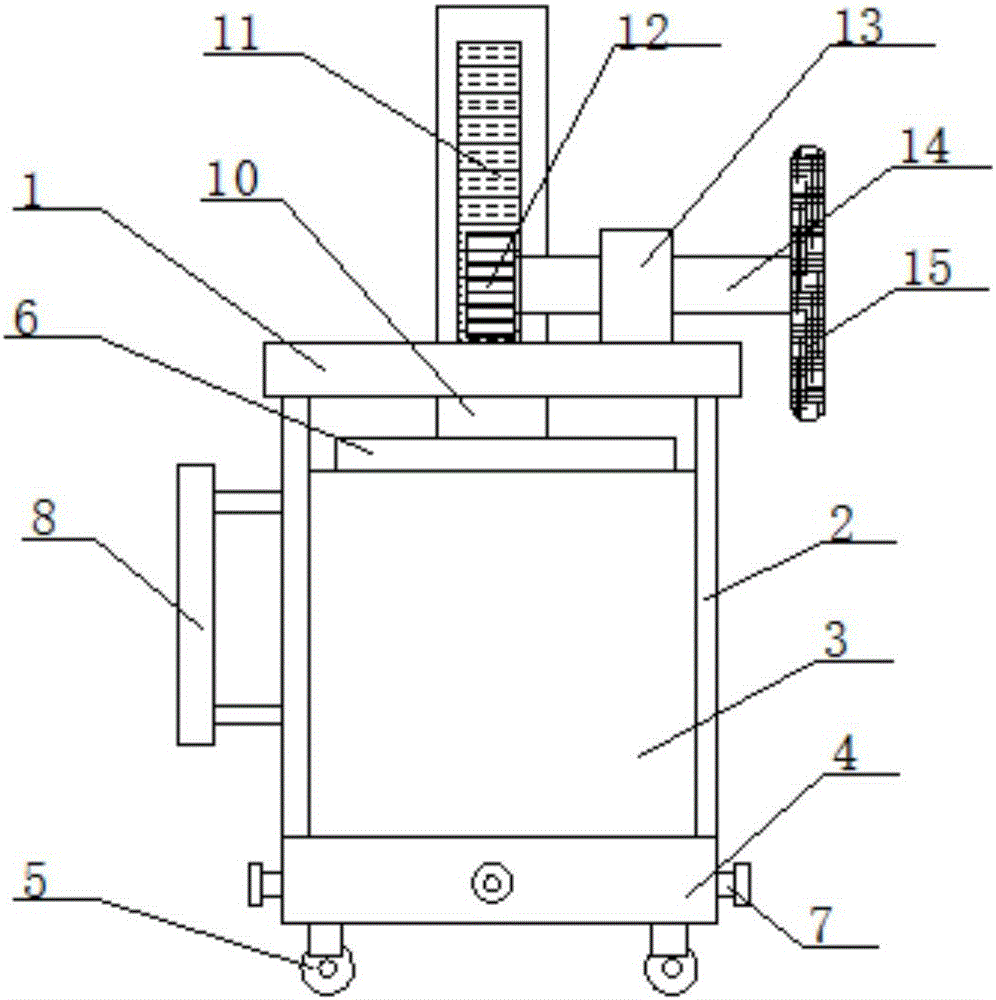
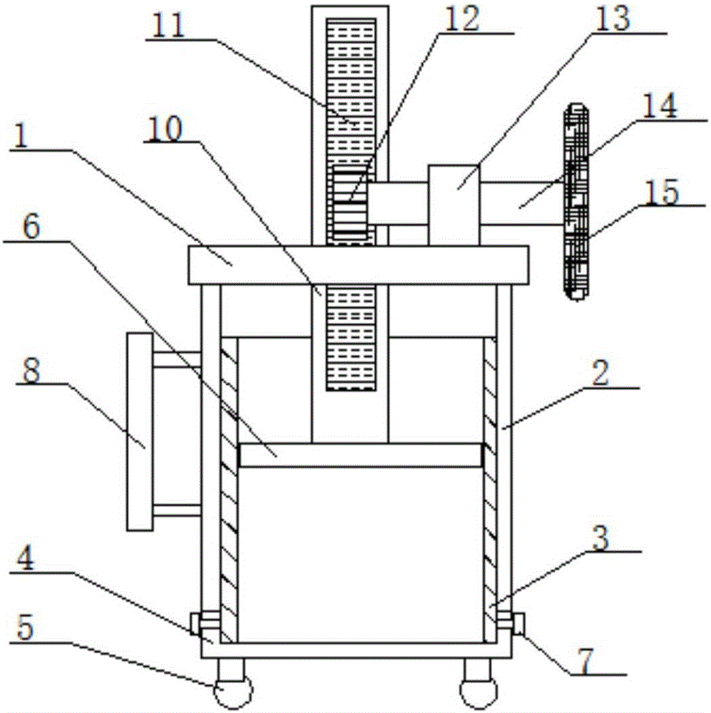
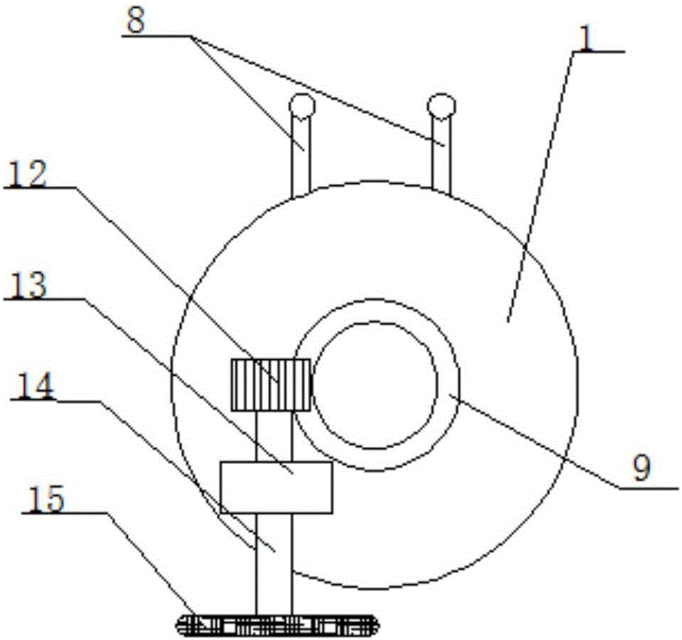
[0016] like figure 1 , figure 2 , image 3 As shown, a small industrial screw processing waste compaction device includes a top plate 1, a support rod 2, a steel cylinder 3, an end cover 4, a universal wheel 5, a pressure plate 6, a connecting pin 7, a push handle 8, and a linear movement Bearing 9, pressure shaft 10, rack 11, gear 12, connecting bearing 13, transmission rod 14, driving handle 15, the bottom of the top plate 1 is fixedly connected with a support rod 2, and one side of the support rod 2 is fixedly connected with Push the handle 8, the bottom of the support rod 2 is fixedly connected with an end cap 4, the inner top of the end cap 4 is provided with a steel cylinder 3, and the outer wall of the end cap 4 is evenly distributed with connecting pins 7, and the steel cylinder 3 and the end cover 4 are fixedly connected by connecting pins 7, the bottom of the ...


PUM


Abstract

The invention relates to a screw machining waste compaction device used in small-scale industry. The screw machining waste compaction device comprises a top plate, a supporting rod, a steel cylinder, an end cap, universal wheels, a pressure plate, connecting pins, a pushing handle, a linear movable bearing, a pressure shaft, a rack, a gear, a connecting bearing, a transmission rod and a driving handle, wherein the bottom of the top plate is fixedly connected with the supporting rod, the pushing handle is fixedly connected to one side of the supporting rod, the bottom of the supporting rod is fixedly connected with the end cap, the steel cylinder is arranged at the top of the inner side of the end cap, and the connecting pins are evenly distributed on the outer wall of the end cap. The screw machining waste compaction device used in the small-scale industry is simple in structure, the pressure shaft can be driven to move by manually turning the driving handle so as to push the pressure plate for movement, then compaction treatment is conducted on machining waste in the steel cylinder, the steel cylinder can be taken down after the connecting pins are taken down, accordingly the compacted machining waste in the end cap can be taken out, and machining waste compaction work can be completed.

Description

technical field [0001] The invention relates to the technical field of industrial equipment, in particular to a small industrial screw processing waste compacting device. Background technique [0002] The screw thread forming work is often processed by small manufacturers or sellers, and after the thread cutting work is completed, a large amount of steel wire waste will inevitably be generated, and the steel wire waste will take up a lot of space, and, although large production plants There are corresponding large-scale recycling equipment, but small manufacturers and sellers need corresponding compaction equipment to compact the screw processing waste, so as to reduce the volume of the waste, so as to facilitate the storage and transfer of waste, and the traditional Compaction equipment often relies on power supply to work, resulting in large compaction equipment and relatively expensive prices. Contents of the invention [0003] The purpose of the present invention is j...

Claims


Application Information

Patent Timeline
IPC IPC(8): B30B9/32B30B1/24
CPCB30B9/327B30B1/24
Inventor 李国朋
Owner 李国朋
Learn More