Washing machine inner tub and washing machine
A washing machine and barrel technology, applied in the field of washing machines, can solve the problems of no flow and low drainage efficiency, and achieve the effects of increasing drainage speed, saving washing time, and improving washing rate
- Summary
- Abstract
- Description
- Claims
- Application Information
AI Technical Summary
Problems solved by technology
Method used
Image

Examples
Embodiment 1
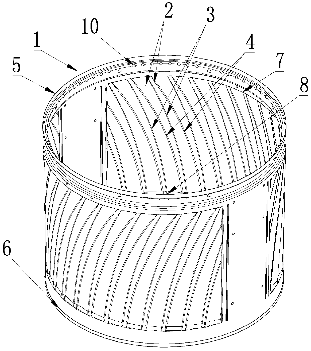
[0040] As shown in the figure, the convex and concave pressure type 2 of the side wall of the inner bucket body described in this embodiment extends in an arc shape from the lowermost end 8 to the uppermost end 7 to one side. The convex and concave pressure type 2 extends rightward and upward from the lowermost end 8 to the uppermost end 7, and the center of the arc-shaped bend is located at the obliquely lower or obliquely upper portion of the arc-shaped bend. Or it can also extend to the uppermost end 7 upwards to the left.
[0041] One of the convex peaks 3 and the valley 4 adjacent to it on one side extend gradually from the lowermost end 8 with a distance until they intersect at one point at the uppermost end, and the convex peak 3 and the valley 4 adjacent to it on the other side There is a distance from the lowermost end to the intersection point, and there is a distance to the uppermost end. At the uppermost end, the concave valley 4 intersects with the convex peak 3 a...
Embodiment 2
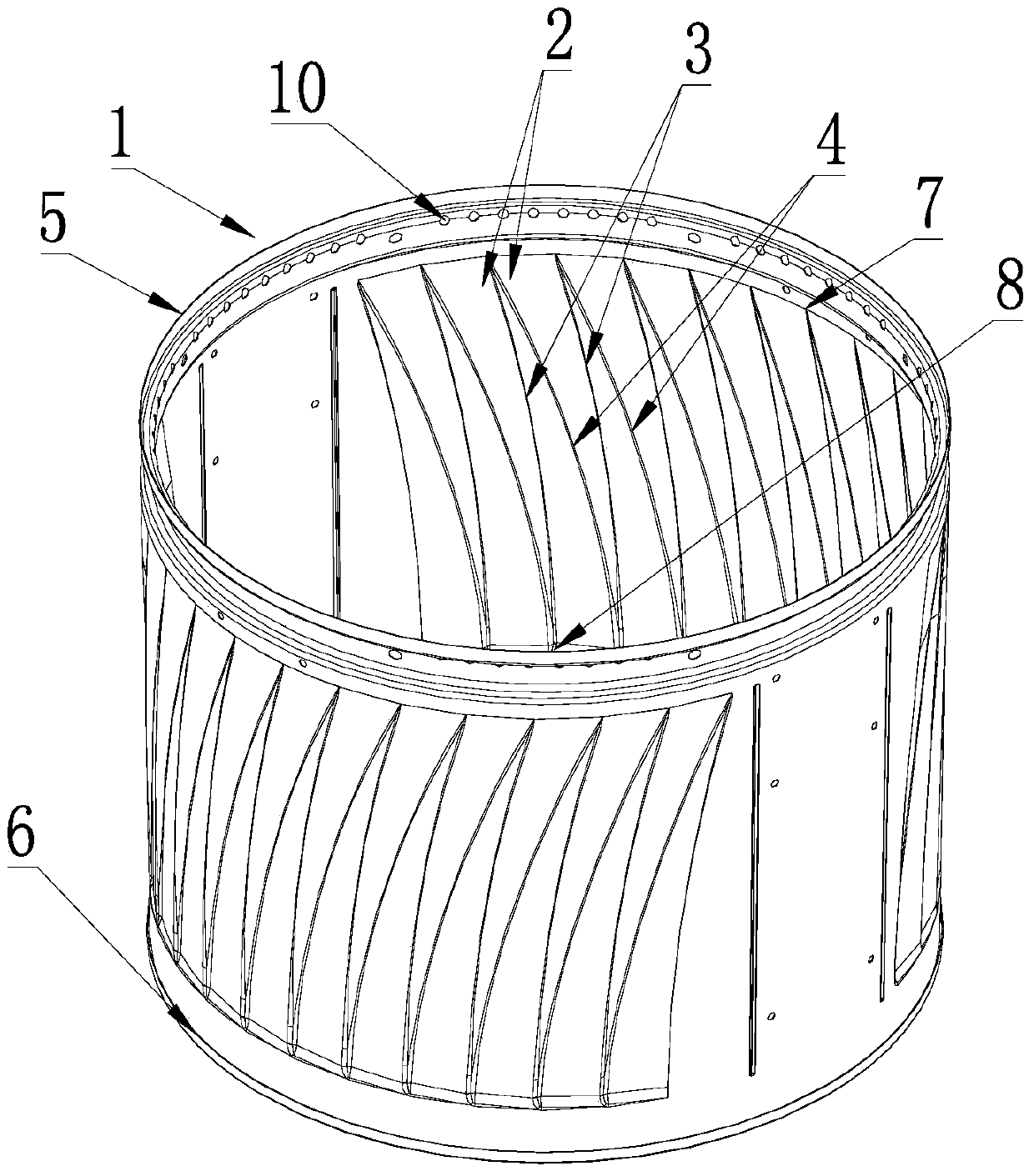
[0044] As shown in the figure, the convex and concave pressure type 2 of the side wall of the inner barrel body 1 of the present invention extends in an arc shape from the lowermost end 8 to the uppermost end 7 to one side. The convex and concave pressure type 2 extends rightward and upward from the lowermost end 8 to the uppermost end 7, and the center of the arc-shaped bend is located at the obliquely lower or obliquely upper portion of the arc-shaped bend. Or it can also extend to the uppermost end 7 upwards to the left.
[0045] One of the convex peaks 3 and the valley 4 adjacent to it on one side extend gradually from the lowermost end 8 with a certain distance, until the uppermost end 7 intersects at one point, the convex peak 3 and the valley adjacent to it on the other side 4. From the lowermost end, the point of intersection extends gradually away from each other, and there is a distance to the uppermost end, and to the uppermost end 7, the concave valley intersects w...
Embodiment 3
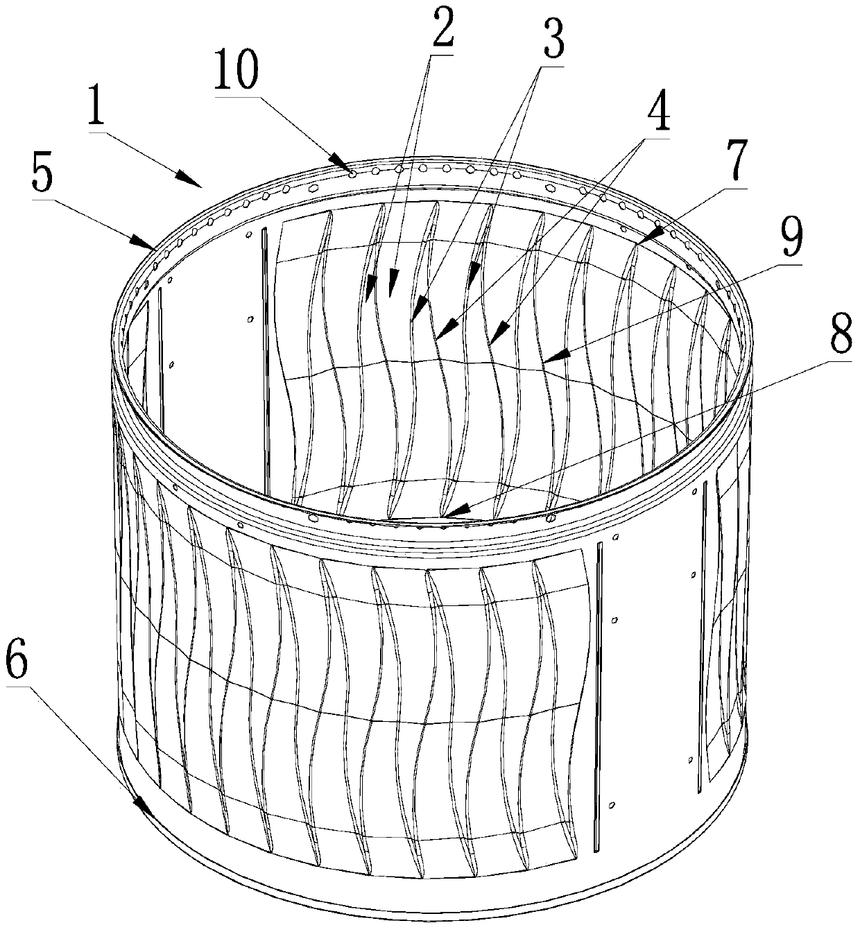
[0048] As shown in the figure, the convex and concave pressure type of the side wall of the inner barrel body 1 of the present invention extend in an arc from the lowermost end 8 to the middle part 9 to one side, and the convex and concave pressure types extend from the middle part 9 to the uppermost end. 7 is curved and extended to the other side, and the two arcs are smoothly transitioned in the middle. The centers of the two sections of arc-shaped bending are respectively located on different sides of the arc-shaped bending.
[0049] The convex peaks 3 of the convex and concave pressure type 2 are convex ribs with a smooth transition, and the two sides of the convex ribs respectively extend smoothly and gradually to the valleys 4 .
[0050] One of the convex peaks 3 and the valley 4 adjacent to it on one side extend gradually from the lowermost end 8 with a certain distance, until the uppermost end 7 intersects at one point, the convex peak 3 and the valley adjacent to it o...
PUM
 Abstract
Description
Claims
Application Information
 - R&D
- Intellectual Property
- Life Sciences
- Materials
- Tech Scout
- Unparalleled Data Quality
- Higher Quality Content
- 60% Fewer Hallucinations
Browse by: Latest US Patents, China's latest patents, Technical Efficacy Thesaurus, Application Domain, Technology Topic, Popular Technical Reports.
© 2025 PatSnap. All rights reserved.Legal|Privacy policy|Modern Slavery Act Transparency Statement|Sitemap|About US| Contact US: help@patsnap.com