
Correction device

A correction device and colonel technology, which is applied in metal processing equipment, forming tools, manufacturing tools, etc., can solve the problems of upper and lower mold deviation, rotation direction deviation, reduction of matching precision between mold base and turret hole, etc., and achieve reliable work and correcting The effect of the angle

Inactive Publication Date: 2017-05-03
YANGZHOU HENGDE IND TECH CO LTD
View PDF1 Cites 0 Cited by
  • Summary
  • Abstract
  • Description
  • Claims
  • Application Information

AI Technical Summary

Problems solved by technology

Due to processing problems, it is easy to have symmetric alignment and coaxiality out-of-tolerance problems during assembly. At the same time, during installation, the keys (grooves) in the mold sleeve cannot guarantee the perpendicularity to the guide rail.
In addition, during the punching process, the matching accuracy of the mold sleeve, mold base and turret hole will be reduced, and there will be a deviation of the coaxiality of the upper mold sleeve and the lower mold base or a deviation in the rotation direction of the upper mold sleeve and the lower mold base, so that the The deviation of the upper and lower molds seriously affects the life of the mold
In addition, for machine tool users, when it is necessary to replace the upper die set, lower die base or related accessories, the accuracy cannot be guaranteed.
[0003] The announcement number announced by the State Intellectual Property Office on October 15, 2008 is CN201132194Y, and the name is "A Correction Device for Upper Die Cover and Lower Die Holder". It can detect and adjust the verticality between the guide rail of the machine tool and the die set

Method used


Image

  • Correction device
  • Correction device
  • Correction device

Examples


Embodiment Construction

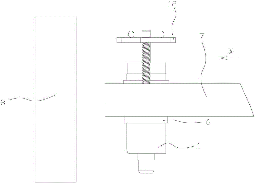
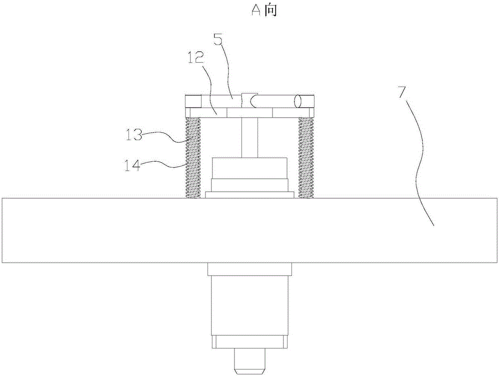
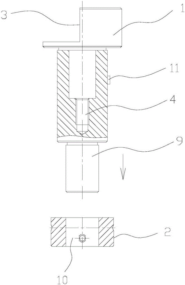
[0017] The invention as Figure 1-3 As shown, it includes an upper calibration rod 1, a lower calibration seat 2 and a dial indicator. The top side of the upper calibration rod 1 is provided with a straight section 3, and the center of the top surface of the upper calibration rod 1 is provided with a threaded hole 4. A threaded handle 5 is connected in the threaded hole 4;

[0018] The upper correction rod 1 is arranged in the middle hole of the upper mold cover 6, and the upper mold cover 6 is arranged on the turntable 7, and a guide rail 8 is provided on one side of the turntable;

[0019] The lower correction seat 2 is arranged in the lower mold base, the bottom of the upper correction rod 1 is provided with a cylindrical platform 9, and the top of the lower correction seat 2 is provided with a cylindrical hole 10 adapted to the cylinder;

[0020] The dial indicator is used for correcting the verticality of the upper die sleeve and the guide rail.

[0021] The upper calib...


PUM


Abstract

The invention relates to a correction device. The correction device, which is simple in structure, suitable for machine tool assembling and also suitable for a machine tool operator to detect and correct the precision of an upper mould sleeve and a lower mould base, is provided. The correction device comprises an upper correction bar, a lower correction base and a dial indicator, wherein a straight section part is arranged on one side of the top of the upper correction bar; a threaded hole is formed in the center of the top surface of the upper correction bar; a handle with thread is arranged in the threaded hole in a connecting way; the upper correction bar is arranged in a middle hole of the upper mould sleeve; the upper mould sleeve is arranged on a turnplate; a guide rail is arranged on one side of the turnplate; the lower correction base is arranged in the lower mould base; a cylindrical platform is arranged at the bottom of the upper correction bar; a cylindrical hole matched with the cylindrical column is formed in the top of the lower correction base; and the dial indicator is used for correcting the verticality of the upper mould sleeve and the guide rail. The correction device has work reliability and can correct angle, symmetry degree and coaxiality.

Description

technical field [0001] The invention relates to a correction device, in particular to a correction device for an upper mold cover and a lower mold seat used on a numerical control punching machine. Background technique [0002] The CNC punching machine and the lower turret are respectively equipped with mold sets and mold bases, and upper and lower molds are respectively installed in the mold sets and mold bases. Due to processing problems, it is easy to have problems of symmetrical alignment and coaxiality out-of-tolerance during assembly. At the same time, during installation, the keys (grooves) in the mold sleeve cannot guarantee the perpendicularity to the guide rail. In addition, during the punching process, the matching accuracy of the mold sleeve, mold base and turret hole will be reduced, and there will be a deviation of the coaxiality of the upper mold sleeve and the lower mold base or a deviation in the rotation direction of the upper mold sleeve and the lower mold...

Claims


Application Information

Patent Timeline
Patent Type & Authority Applications(China)
IPC IPC(8): B21D37/14
Inventor 卞正文庄瑞斌王利平佘佳宰广平
Owner YANGZHOU HENGDE IND TECH CO LTD
Learn More