
Tensile shear rheometer and method for testing rheological properties of alloy solid-liquid two-phase region by using tensile shear rheometer

Inactive Publication Date: 2017-04-26
HARBIN INST OF TECH
View PDF6 Cites 3 Cited by
  • Summary
  • Abstract
  • Description
  • Claims
  • Application Information

AI Technical Summary

Problems solved by technology

However, this method is not suitable for semi-solid rheological problems with low solid phase ratio, because the melt is easy to slide relative to the tie rod, the measured displacement is larger than the real value, and the calculation method of Olivier Ludwig is relatively rough

Method used


Image

  • Tensile shear rheometer and method for testing rheological properties of alloy solid-liquid two-phase region by using tensile shear rheometer
  • Tensile shear rheometer and method for testing rheological properties of alloy solid-liquid two-phase region by using tensile shear rheometer
  • Tensile shear rheometer and method for testing rheological properties of alloy solid-liquid two-phase region by using tensile shear rheometer

Examples


specific Embodiment approach 1

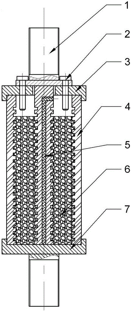
[0019] Specific implementation mode one: as figure 1 As shown, a tensile shear rheometer in this embodiment is composed of a tie rod 1, a positioning pin 2, an upper end cover 3, a crucible 4, a high alumina fiber 5 and a lower end cover 7; the upper port of the crucible 4 is provided with an upper end Cover 3, the lower port of the crucible 4 is provided with a lower end cover 7; the upper part of the pull rod 1 is provided with a boss and two holes are punched on the boss, and the upper end cover 3 is provided with two holes on the boss. The hole matched with the hole, and the positioning pin 2 forms a clearance fit. The center of the upper end cover 3 also has a through hole. The lower part of the pull rod 1 passes through the through hole of the upper end cover 3 and is arranged in the crucible 4 and connected with the lower end. The upper surface of the cover 7 contacts, and the boss on the pull rod 1 is stuck on the upper surface of the upper end cover 3; the lower end o...

specific Embodiment approach 2

[0025] Embodiment 2: This embodiment differs from Embodiment 1 in that: the groove is a right-angle groove, an oblique groove or a screw thread. Others are the same as in the first embodiment.

[0026] In this embodiment, grooves are provided on the tie rod 1 to prevent the solid-liquid mixed melt from sliding relative to the molten metal during deformation.

specific Embodiment approach 3

[0027] Embodiment 3: This embodiment differs from Embodiment 1 or Embodiment 2 in that: the pull rod 1 is a column structure. Others are the same as in the first or second embodiment.


PUM


Abstract

The invention discloses a tensile shear rheometer and a method for testing rheological properties of an alloy solid-liquid two-phase region by using the tensile shear rheometer, and relates to the tensile shear rheometer and the method for testing the rheological properties of the alloy solid-liquid two-phase region by using the tensile shear rheometer. The invention aims at improving the accuracy and efficiency of a conventional method for testing rheological properties of an alloy solid-liquid two-phase region. The tensile shear rheometer is composed of a pull bar, a positioning pin, an upper end cover, a crucible, a high-aluminum fiber, and a lower end cover. Then, a molten metal liquid flows into the rheometer and is cooled to prepare a rheological test specimen; finally, creep properties of the alloy melt are tested on a high-temperature creepmeter, and the rheological properties of the alloy in the solid-liquid two-phase region are obtained. The method can more accurately measure the rheological properties of the alloy in the solid-liquid two-phase region, the specimen only needs to be prepared in the method, and a used loading device and heating device are both realized in the high-temperature creepmeter; the method is simple and easy to control, and easy to popularize.

Description

technical field [0001] The invention relates to a tensile shear rheometer and a method for testing the rheological properties of an alloy in a solid-liquid two-phase region by using the tensile shear rheometer. Background technique [0002] At present, there are many rheological testing methods. For low-viscosity fluids, concentric drum viscometers, capillary viscometers, and flow cup methods can be used to measure the rheological properties; for samples with high viscosity or strong viscoelasticity, Both parallel plate and falling ball shear rheometers can be used. [0003] There are two main methods for testing the rheological properties of the high temperature, high viscosity, high yield stress viscoelastic plastic in the solid-liquid two-phase region of the alloy: one is the rheological property test method of the concentric drum viscometer, This method is suitable for measuring the apparent viscosity of alloys, but this research method of alloy rheology has certain lim...

Claims


Application Information

Patent Timeline
Patent Type & Authority Applications(China)
IPC IPC(8): G01N11/00
CPCG01N11/00G01N2011/006
Inventor 王汝佳吴士平陈伟
Owner HARBIN INST OF TECH
Learn More